Toyota Tacoma (2015-2018) Service Manual: IG Power Source Circuit
DESCRIPTION
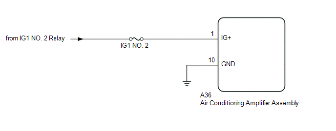
The main power source is supplied to the air conditioning amplifier assembly when the ignition switch is turned to ON.
The power is used for operating the air conditioning amplifier assembly, servo motors, etc.
WIRING DIAGRAM
CAUTION / NOTICE / HINT
NOTICE:
Inspect the fuses for circuits related to this system before performing the following inspection procedure.
PROCEDURE
|
1. |
CHECK HARNESS AND CONNECTOR (AIR CONDITIONING AMPLIFIER ASSEMBLY - IG POWER SOURCE) |
(a) Disconnect the A36 air conditioning amplifier assembly connector.
(b) Measure the voltage according to the value(s) in the table below.
Standard Voltage:
|
Tester Connection |
Switch Condition |
Specified Condition |
|---|---|---|
|
A36-1 (IG+) - Body ground |
Ignition switch off |
Below 1 V |
|
A36-1 (IG+) - Body ground |
Ignition switch ON |
11 to 14 V |
| NG | .gif) |
REPAIR OR REPLACE HARNESS OR CONNECTOR |
|
.gif)
|
2. |
CHECK HARNESS AND CONNECTOR (AIR CONDITIONING AMPLIFIER ASSEMBLY - BODY GROUND) |
(a) Disconnect the A36 air conditioning amplifier assembly connector.
(b) Measure the resistance according to the value(s) in the table below.
Standard Resistance:
|
Tester Connection |
Condition |
Specified Condition |
|---|---|---|
|
A36-10 (GND) - Body ground |
Always |
Below 1 Ω |
| OK | |
PROCEED TO NEXT SUSPECTED AREA SHOWN IN PROBLEM SYMPTOMS TABLE |
| NG | |
REPAIR OR REPLACE HARNESS OR CONNECTOR |
 Blower Motor Circuit
DESCRIPTION
The blower motor with fan sub-assembly operates according to signals from the
air conditioning amplifier assembly. The blower motor with fan sub-assembly speed
signals are transmitted ...
 PTC Heater Circuit
DESCRIPTION
PTC HTR heater relays are closed in accordance with signals from the air conditioning
amplifier assembly and power is supplied to the quick heater assembly installed
on the radiator h ...
Other materials:
Steering Pad Switch Circuit
DESCRIPTION
The forward recognition camera receives a lane departure alert switch signal
from the steering pad switch assembly.
WIRING DIAGRAM
for 2TR-FE
for 2GR-FKS
CAUTION / NOTICE / HINT
NOTICE:
The vehicle is equipped with a Supplemental Restraint System (SRS) which includes
compo ...
Precaution
PRECAUTION
1. IGNITION SWITCH EXPRESSIONS
(a) The type of ignition switch used on this model differs according to the specifications
of the vehicle. The expressions listed in the table below are used in this section.
Expression
Ignition Switch (Position)
Engine ...
Transmitter ID not Registered (C2171/71)
DESCRIPTION
The IDs of each tire pressure warning valve and transmitter are registered to
the tire pressure warning ECU and receiver.
When the ECU detects that a transmitter ID code is not registered in the ECU,
this DTC is stored.
DTC No.
Detection Item
DTC D ...
