Toyota Tacoma (2015-2018) Service Manual: Removal
REMOVAL
CAUTION / NOTICE / HINT
HINT:
- Use the same procedure for both the RH and LH sides.
- The procedure described below is for the LH side.
PROCEDURE
1. PRECAUTION
NOTICE:
After turning the ignition switch off, waiting time may be required before disconnecting the cable from the negative (-) battery terminal. Therefore, make sure to read the disconnecting the cable from the negative (-) battery terminal notices before proceeding with work.
Click here .gif)
2. DISCONNECT CABLE FROM NEGATIVE BATTERY TERMINAL
CAUTION:
Wait at least 90 seconds after disconnecting the cable from the negative (-) battery terminal to disable the SRS system.
NOTICE:
When disconnecting the cable, some systems need to be initialized after the cable is reconnected.
Click here
3. REMOVE ACCESS PANEL REAR WEATHERSTRIP
Click here
4. REMOVE LAP BELT OUTER ANCHOR COVER
Click here
5. REMOVE ACCESS PANEL INSIDE HANDLE BEZEL
Click here
6. REMOVE DOOR PULL HANDLE
Click here
7. REMOVE REAR DOOR TRIM BOARD SUB-ASSEMBLY
Click here
8. REMOVE ACCESS PANEL INSIDE HANDLE SUB-ASSEMBLY
Click here
9. REMOVE FRONT SEAT OUTER BELT ASSEMBLY
|
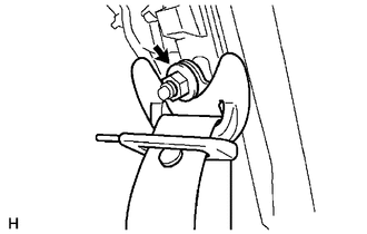
(a) Remove the nut to disconnect the shoulder anchor. |
|
|
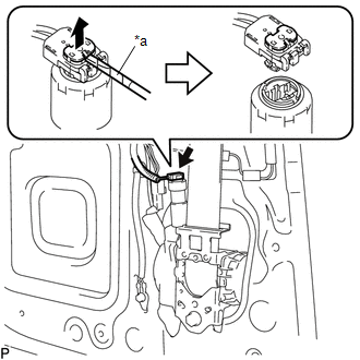
(b) Using a screwdriver with its tip wrapped in protective tape, release the locking button to disconnect the connector. Text in Illustration
|
|
|
(c) Remove the 2 bolts. |
|
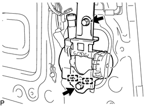
(d) Disengage the 2 guides to remove the front seat outer belt assembly.
10. REMOVE FRONT SHOULDER BELT ANCHOR ADJUSTER ASSEMBLY
|
(a) Remove the bolt. |
|
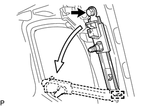
(b) Disengage the guide to remove the front shoulder belt anchor adjuster assembly as shown in the illustration.
 Installation
INSTALLATION
CAUTION / NOTICE / HINT
HINT:
Use the same procedure for both the RH and LH sides.
The procedure described below is for the LH side.
PROCEDURE
1. INSTALL FRONT SHOU ...

Other materials:
GPS Mark is not Displayed
PROCEDURE
1.
CHECK CABIN
(a) Check the cabin for any object that might interrupt radio reception or additional
devices which use radio waves on the instrument panel. If such an object exists,
remove it and check if the GPS mark reappears.
HINT:
The GPS uses ex ...
Skid Control Buzzer Circuit (C1A4A)
DESCRIPTION
Based on dynamic radar cruise control system operation, the forward recognition
camera provides warnings to the driver by sounding the skid control buzzer.
DTC C1A4A is stored when a malfunction is detected in the skid control buzzer
circuit.
DTC No.
Detectio ...
Operation Check
OPERATION CHECK
1. CHECK NAVIGATION SYSTEM NORMAL CONDITION
(a) If the symptom is applicable to any of the following, it is intended behavior,
and not a malfunction.
Symptom
Answer
A longer route than expected is chosen.
Depending on the road co ...
