Toyota Tacoma (2015-2018) Service Manual: Check Bus 5 Line for Short to +B
DESCRIPTION
There may be a short circuit between one of the CAN bus lines and +B when no resistance exists between terminal 15 (CA5H) of the central gateway ECU (network gateway ECU) and terminal 16 (BAT) of the DLC3, or terminal 16 (CA5L) of the central gateway ECU (network gateway ECU) and terminal 16 (BAT) of the DLC3.
|
Detection Item |
Trouble Area |
|---|---|
|
No resistance exists between terminal 15 (CA5H) of the central gateway ECU (network gateway ECU) and terminal 16 (BAT) of the DLC3, or terminal 16 (CA5L) of the central gateway ECU (network gateway ECU) and terminal 16 (BAT) of the DLC3. |
|
- *1: w/ Toyota Safety Sense P
- *2: w/ Intuitive Parking Assist System
- *3: w/ Blind Spot Monitor System
WIRING DIAGRAM
.png)
CAUTION / NOTICE / HINT
CAUTION:
When performing the confirmation driving pattern, obey all speed limits and traffic laws.
NOTICE:
- Because the order of diagnosis is important to allow correct diagnosis,
make sure to begin troubleshooting using How to Proceed with Troubleshooting
when CAN communication system related DTCs are output.
Click here
.gif)
- Before measuring the resistance of the CAN bus, turn the ignition switch off and leave the vehicle for 1 minute or more without operating the key or any switches, or opening or closing the doors. After that, disconnect the cable from the negative (-) battery terminal and leave the vehicle for 1 minute or more before measuring the resistance.
- After turning the ignition switch off, waiting time may be required
before disconnecting the cable from the negative (-) battery terminal. Therefore,
make sure to read the disconnecting the cable from the negative (-) battery
terminal notices before proceeding with work.
Click here
- Some parts must be initialized and set when replacing or removing and
installing parts.
Click here
- After performing repairs, perform the DTC check procedure and confirm
that the DTCs are not output again.
DTC check procedure: Turn the ignition switch to ON and wait for 1 minute or more. Then operate the suspected malfunctioning system and drive the vehicle at 60 km/h (37 mph) or more for 5 minutes or more.
- After the repair, perform the CAN bus check and check that all the ECUs
and sensors connected to the CAN communication system are displayed as normal.
Click here
HINT:
- Before disconnecting related connectors for inspection, push in on each connector body to check that the connector is not loose or disconnected.
- When a connector is disconnected, check that the terminals and connector body are not cracked, deformed or corroded.
PROCEDURE
|
1. |
CHECK FOR SHORT TO +B IN CAN BUS LINE (NO. 6 CAN JUNCTION CONNECTOR) |
(a) Disconnect the cable from the negative (-) battery terminal.
(b) Disconnect the No. 6 CAN junction connector.
(c) Measure the resistance according to the value(s) in the table below.
|
*1 |
DLC3 |
- |
- |
|
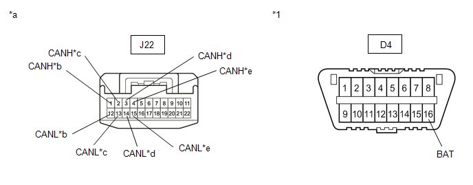
*a |
Front view of wire harness connector (to No. 6 CAN Junction Connector) |
*b |
to Clearance Warning ECU Assembly (w/ Intuitive Parking Assist System) |
|
*c |
to Central Gateway ECU (Network Gateway ECU) |
*d |
to No. 5 CAN Junction Connector |
|
*e |
to Forward Recognition Camera (w/ Toyota Safety Sense P) |
- |
- |
Standard Resistance:
|
Tester Connection |
Condition |
Specified Condition |
Connected to |
|---|---|---|---|
|
J22-1 (CANH) - D4-16 (BAT) |
Cable disconnected from negative (-) battery terminal |
6 kΩ or higher |
Clearance warning ECU assembly*1 |
|
J22-12 (CANL) - D4-16 (BAT) |
|||
|
J22-2 (CANH) - D4-16 (BAT) |
Cable disconnected from negative (-) battery terminal |
6 kΩ or higher |
Central gateway ECU (network gateway ECU) |
|
J22-13 (CANL) - D4-16 (BAT) |
|||
|
J22-3 (CANH) - D4-16 (BAT) |
Cable disconnected from negative (-) battery terminal |
6 kΩ or higher |
No. 5 CAN junction connector |
|
J22-14 (CANL) - D4-16 (BAT) |
|||
|
J22-4 (CANH) - D4-16 (BAT) |
Cable disconnected from negative (-) battery terminal |
6 kΩ or higher |
Forward recognition camera*2 |
|
J22-15 (CANL) - D4-16 (BAT) |
- *1: w/ Intuitive Parking Assist System
- *2: w/ Toyota Safety Sense P
|
Result |
Proceed to |
|---|---|
|
OK |
A |
|
NG (Central gateway ECU (network gateway ECU) CAN main line) |
B |
|
NG (No. 5 CAN junction connector CAN main line) |
C |
|
NG (ECU or sensor CAN branch lines) |
D |
| A | .gif) |
REPLACE NO. 6 CAN JUNCTION CONNECTOR |
| C | |
GO TO STEP 3 |
| D | |
GO TO STEP 6 |
|
.gif)
|
2. |
CHECK FOR SHORT TO +B IN CAN BUS LINE (NO. 6 CAN JUNCTION CONNECTOR - CENTRAL GATEWAY ECU (NETWORK GATEWAY ECU)) |
(a) Disconnect the N36 central gateway ECU (network gateway ECU) connector.
(b) Measure the resistance according to the value(s) in the table below.
|
*1 |
DLC3 |
- |
- |
|
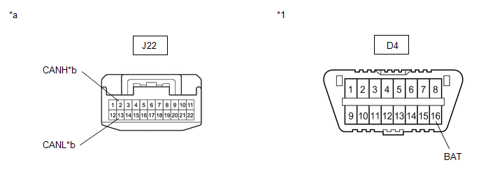
*a |
Front view of wire harness connector (to No. 6 CAN Junction Connector) |
*b |
to Central Gateway ECU (Network Gateway ECU) |
Standard Resistance:
|
Tester Connection |
Condition |
Specified Condition |
|---|---|---|
|
J22-2 (CANH) - D4-16 (BAT) |
Cable disconnected from negative (-) battery terminal |
6 kΩ or higher |
|
J22-13 (CANL) - D4-16 (BAT) |
| OK | |
REPLACE CENTRAL GATEWAY ECU (NETWORK GATEWAY ECU) |
| NG | |
REPAIR OR REPLACE CAN MAIN BUS LINE OR CONNECTOR (NO. 6 CAN JUNCTION CONNECTOR - CENTRAL GATEWAY ECU (NETWORK GATEWAY ECU)) |
|
3. |
CHECK FOR SHORT TO +B IN CAN BUS LINE (NO. 5 CAN JUNCTION CONNECTOR) |
(a) Disconnect the No. 5 CAN junction connector.
(b) Measure the resistance according to the value(s) in the table below.
|
*1 |
DLC3 |
- |
- |
|
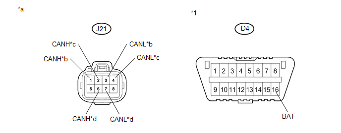
*a |
Front view of wire harness connector (to No. 5 CAN Junction Connector) |
*b |
to Millimeter Wave Radar Sensor Assembly (w/ Toyota Safety Sense P) |
|
*c |
to No. 6 CAN Junction Connector |
*d |
to No. 4 CAN Junction Connector |
Standard Resistance:
|
Tester Connection |
Condition |
Specified Condition |
Connected to |
|---|---|---|---|
|
J21-1 (CANH) - D4-16 (BAT) |
Cable disconnected from negative (-) battery terminal |
6 kΩ or higher |
Millimeter wave radar sensor assembly*1 |
|
J21-3 (CANL) - D4-16 (BAT) |
|||
|
J21-2 (CANH) - D4-16 (BAT) |
Cable disconnected from negative (-) battery terminal |
6 kΩ or higher |
No. 6 CAN junction connector |
|
J21-4 (CANL) - D4-16 (BAT) |
|||
|
J21-6 (CANH) - D4-16 (BAT) |
Cable disconnected from negative (-) battery terminal |
6 kΩ or higher |
No. 4 CAN junction connector |
|
J21-7 (CANL) - D4-16 (BAT) |
- *1: w/ Toyota Safety Sense P
|
Result |
Proceed to |
|---|---|
|
OK |
A |
|
NG (No. 4 CAN junction connector CAN main line) |
B |
|
NG (No. 6 CAN junction connector CAN main line) |
C |
|
NG (ECU or sensor CAN branch lines) |
D |
| A | |
REPLACE NO. 5 CAN JUNCTION CONNECTOR |
| C | |
REPAIR OR REPLACE CAN MAIN BUS LINE OR CONNECTOR (NO. 5 CAN JUNCTION CONNECTOR - NO. 6 CAN JUNCTION CONNECTOR) |
| D | |
GO TO STEP 6 |
|
|
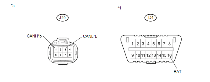
4. |
CHECK FOR SHORT TO +B IN CAN BUS LINE (NO. 4 CAN JUNCTION CONNECTOR) |
(a) Disconnect the No. 4 CAN junction connector.
(b) Measure the resistance according to the value(s) in the table below.
|
*1 |
DLC3 |
- |
- |
|
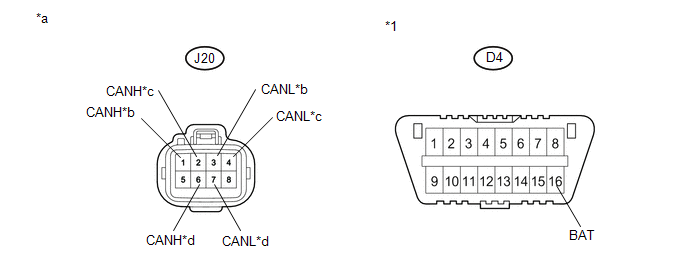
*a |
Front view of wire harness connector (to No. 4 CAN Junction Connector) |
*b |
to Central Gateway ECU (Network Gateway ECU) |
|
*c |
to No. 5 CAN Junction Connector |
*d |
to Blind Spot Monitor Sensor LH (w/ Blind Spot Monitor System) |
Standard Resistance:
|
Tester Connection |
Condition |
Specified Condition |
Connected to |
|---|---|---|---|
|
J20-1 (CANH) - D4-16 (BAT) |
Cable disconnected from negative (-) battery terminal |
6 kΩ or higher |
Central gateway ECU (network gateway ECU) |
|
J20-3 (CANL) - D4-16 (BAT) |
|||
|
J20-2 (CANH) - D4-16 (BAT) |
Cable disconnected from negative (-) battery terminal |
6 kΩ or higher |
No. 5 CAN junction connector |
|
J20-4 (CANL) - D4-16 (BAT) |
|||
|
J20-6 (CANH) - D4-16 (BAT) |
Cable disconnected from negative (-) battery terminal |
6 kΩ or higher |
Blind spot monitor sensor LH*1 |
|
J20-7 (CANL) - D4-16 (BAT) |
- *1: w/ Blind Spot Monitor System
|
Result |
Proceed to |
|---|---|
|
OK |
A |
|
NG (Central gateway ECU (network gateway ECU) CAN main line) |
B |
|
NG (No. 5 CAN junction connector CAN main line) |
C |
|
NG (ECU or sensor CAN branch lines) |
D |
| A | |
REPLACE NO. 4 CAN JUNCTION CONNECTOR |
| C | |
REPAIR OR REPLACE CAN MAIN BUS LINE OR CONNECTOR (NO. 4 CAN JUNCTION CONNECTOR - NO. 5 CAN JUNCTION CONNECTOR) |
| D | |
GO TO STEP 6 |
|
|
5. |
CHECK FOR SHORT TO +B IN CAN BUS LINE (NO. 4 CAN JUNCTION CONNECTOR - CENTRAL GATEWAY ECU (NETWORK GATEWAY ECU)) |
(a) Disconnect the N36 central gateway ECU (network gateway ECU) connector.
(b) Measure the resistance according to the value(s) in the table below.
|
*1 |
DLC3 |
- |
- |
|
*a |
Front view of wire harness connector (to No. 4 CAN Junction Connector) |
*b |
to Central Gateway ECU (Network Gateway ECU) |
Standard Resistance:
|
Tester Connection |
Condition |
Specified Condition |
|---|---|---|
|
J20-1 (CANH) - D4-16 (BAT) |
Cable disconnected from negative (-) battery terminal |
6 kΩ or higher |
|
J20-3 (CANL) - D4-16 (BAT) |
| OK | |
REPLACE CENTRAL GATEWAY ECU (NETWORK GATEWAY ECU) |
| NG | |
REPAIR OR REPLACE CAN MAIN BUS LINE OR CONNECTOR (NO. 4 CAN JUNCTION CONNECTOR - CENTRAL GATEWAY ECU (NETWORK GATEWAY ECU)) |
|
6. |
CHECK FOR SHORT TO B+ IN CAN BUS LINES (ECU, SENSOR) |
|
(a) Reconnect the CAN junction connector. |
|
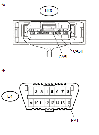
(b) Disconnect the connector that includes terminals CANH and CANL from the ECU or sensor to which the bus line shorted to +B is connected
(c) Measure the resistance according to the value(s) in the table below.
Standard Resistance:
|
Tester Connection |
Condition |
Specified Condition |
|---|---|---|
|
N36-15 (CA5H) - D4-16 (BAT) |
Cable disconnected from negative (-) battery terminal |
6 kΩ or higher |
|
N36-16 (CA5L) - D4-16 (BAT) |
Cable disconnected from negative (-) battery terminal |
6 kΩ or higher |
HINT:
If the resistance changes to 6 kΩ or higher when the connector is disconnected from the ECU or sensor, there may be a short in the ECU or sensor.
| OK | |
REPLACE ECU OR SENSOR |
| NG | |
REPAIR OR REPLACE HARNESS OR CONNECTOR |
 Check Bus 5 Lines for Short Circuit
DESCRIPTION
There may be a short circuit between the CAN main bus lines and/or CAN branch
lines when the resistance between terminals 15 (CA5H) and 16 (CA5L) of the central
gateway ECU (network g ...
 Check Bus 5 Line for Short to GND
DESCRIPTION
There may be a short circuit between one of the CAN bus lines and GND when there
is no resistance between terminal 15 (CA5H) of the central gateway ECU (network
gateway ECU) and termi ...
Other materials:
Removal
REMOVAL
PROCEDURE
1. REMOVE NO. 2 ENGINE UNDER COVER SUB-ASSEMBLY (w/ Off Road Package)
2. REMOVE NO. 1 ENGINE UNDER COVER SUB-ASSEMBLY
3. DRAIN ENGINE COOLANT
4. REMOVE V-BANK COVER SUB-ASSEMBLY
5. REMOVE RADIATOR SUPPORT TO FRAME SEAL
(a) Remove the 7 clips and radiator su ...
Outside rear view mirrors
Mirror angle can be adjusted.
Power-adjustable type
Select a mirror to adjust.
(L: left or R: right)
Adjust the mirror up, down, in or
out using the switch.
Manually adjustable type
Adjust the mirror up, down, in or out by pushing the mirror surface.
Folding back the mirrors
...
A/C ECU Vehicle Information Reading/Writing Processor Malfunction (B15F5)
DESCRIPTION
This DTC is stored when items controlled by the air conditioning amplifier assembly
cannot be customized via the audio and visual system vehicle customization screen.
HINT:
The air conditioning amplifier assembly controls the air conditioning system
related items that are customiz ...
