Toyota Tacoma (2015-2018) Service Manual: Removal
REMOVAL
PROCEDURE
1. REMOVE NO. 2 ENGINE UNDER COVER SUB-ASSEMBLY (w/ Off Road Package)
2. REMOVE NO. 1 ENGINE UNDER COVER SUB-ASSEMBLY
3. DRAIN ENGINE COOLANT
.gif)
4. REMOVE V-BANK COVER SUB-ASSEMBLY
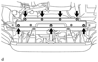
5. REMOVE RADIATOR SUPPORT TO FRAME SEAL
|
(a) Remove the 7 clips and radiator support to frame seal. |
|
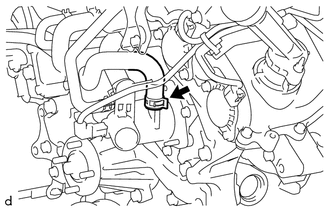
6. DISCONNECT NO. 2 RADIATOR HOSE
|
(a) Slide the hose clip and disconnect the No. 2 radiator hose from the water inlet with thermostat sub-assembly. |
|
.png)
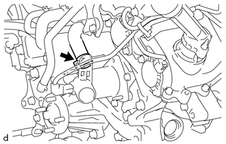
7. DISCONNECT NO. 7 WATER BY-PASS HOSE (w/ Oil Cooler)
|
(a) Slide the hose clip and disconnect the No. 7 water by-pass hose from the water inlet with thermostat sub-assembly. |
|
8. DISCONNECT NO. 4 WATER BY-PASS HOSE
|
(a) Slide the hose clip and disconnect the No. 4 water by-pass hose from the water inlet with thermostat sub-assembly. |
|
9. DISCONNECT NO. 3 WATER BY-PASS HOSE
|
(a) Slide the hose clip and disconnect the No. 3 water by-pass hose from the water inlet with thermostat sub-assembly. |
|
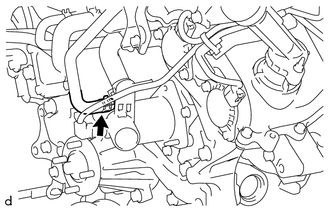
10. REMOVE WATER INLET WITH THERMOSTAT SUB-ASSEMBLY
HINT:
If the thermostat was not installed, cooling efficiency would decrease. Even if the engine tends to overheat, do not remove the thermostat.
|
(a) Disconnect the connector from the water inlet with thermostat sub-assembly. |
|
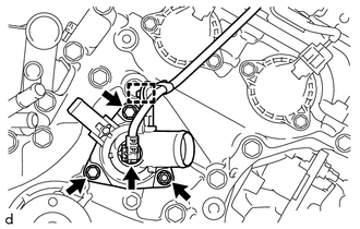
(b) Disengage the clamp to separate the wire harness.
(c) Remove the 2 bolts, nut and water inlet with thermostat sub-assembly from the timing chain cover assembly.
|
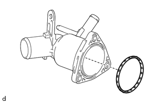
(d) Remove the gasket from the water inlet with thermostat sub-assembly. |
|
 Components
COMPONENTS
ILLUSTRATION
ILLUSTRATION
ILLUSTRATION
...
 Inspection
INSPECTION
PROCEDURE
1. INSPECT WATER INLET WITH THERMOSTAT SUB-ASSEMBLY
HINT:
The valve opening temperature is inscribed on the water inlet with thermostat
sub-assembly.
(a) Immerse the ther ...
Other materials:
Four Wheel Drive (4WD) Range Signal Circuit Range / Performance (P279E)
DESCRIPTION
When the transfer position switch is switched, the 2-4 terminal and LO terminal
change to one of the following ON/OFF combinations listed in the table below.
Terminal
2WD
Between 2WD and H4
H4
Between H4 and L4
L4
...
Speedometer Malfunction
DESCRIPTION
The meter CPU receives vehicle speed signals from the skid control ECU via the
CAN communication system (CAN V1 Bus). The speed sensor detects the wheel speed
and sends the appropriate signals to the skid control ECU. The skid control ECU
supplies power to the vehicle speed sensor ...
Cruise Control Input Processor (P160700)
DESCRIPTION
The ECM continuously monitors its main and sub CPUs. This self-check ensures
that the ECM is functioning properly. If outputs from the CPUs are different and
deviate from the standard, the ECM will illuminate the MIL and store the DTC.
DTC No.
Detection Item
...
