Toyota Tacoma (2015-2018) Service Manual: Check Bus 5 Lines for Short Circuit
DESCRIPTION
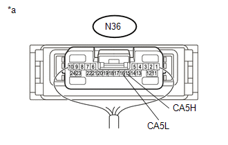
There may be a short circuit between the CAN main bus lines and/or CAN branch lines when the resistance between terminals 15 (CA5H) and 16 (CA5L) of the central gateway ECU (network gateway ECU) is below 54 Ω.
|
Detection Item |
Trouble Area |
|---|---|
|
Resistance between terminals 15 (CA5H) and 16 (CA5L) of central gateway ECU (network gateway ECU) is below 54 Ω. |
|
- *1: w/ Toyota Safety Sense P
- *2: w/ Intuitive Parking Assist System
- *3: w/ Blind Spot Monitor System
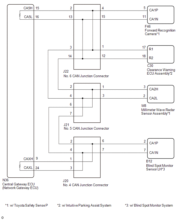
WIRING DIAGRAM
CAUTION / NOTICE / HINT
CAUTION:
When performing the confirmation driving pattern, obey all speed limits and traffic laws.
NOTICE:
- Because the order of diagnosis is important to allow correct diagnosis,
make sure to begin troubleshooting using How to Proceed with Troubleshooting
when CAN communication system related DTCs are output.
Click here
.gif)
- Before measuring the resistance of the CAN bus, turn the ignition switch off and leave the vehicle for 1 minute or more without operating the key or any switches, or opening or closing the doors. After that, disconnect the cable from the negative (-) battery terminal and leave the vehicle for 1 minute or more before measuring the resistance.
- After turning the ignition switch off, waiting time may be required
before disconnecting the cable from the negative (-) battery terminal. Therefore,
make sure to read the disconnecting the cable from the negative (-) battery
terminal notices before proceeding with work.
Click here
- Some parts must be initialized and set when replacing or removing and
installing parts.
Click here
- After performing repairs, perform the DTC check procedure and confirm
that the DTCs are not output again.
DTC check procedure: Turn the ignition switch to ON and wait for 1 minute or more. Then operate the suspected malfunctioning system and drive the vehicle at 60 km/h (37 mph) or more for 5 minutes or more.
- After the repair, perform the CAN bus check and check that all the ECUs
and sensors connected to the CAN communication system are displayed as normal.
Click here
HINT:
- Before disconnecting related connectors for inspection, push in on each connector body to check that the connector is not loose or disconnected.
- When a connector is disconnected, check that the terminals and connector body are not cracked, deformed or corroded.
PROCEDURE
|
1. |
CHECK FOR SHORT IN CAN BUS LINES (NO. 6 CAN JUNCTION CONNECTOR) |
(a) Disconnect the cable from the negative (-) battery terminal.
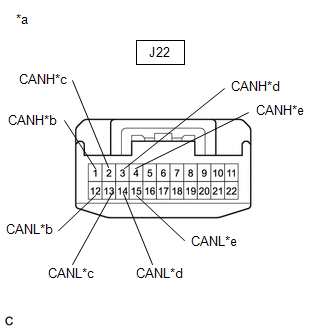
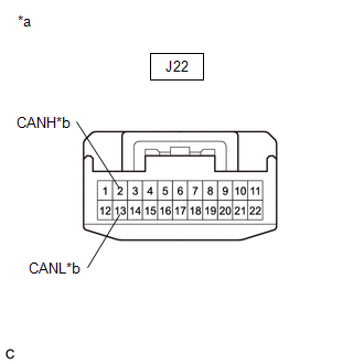
(b) Disconnect the No. 6 CAN junction connector.
|
(c) Measure the resistance according to the value(s) in the table below. Standard Resistance:
|
|
|
Result |
Proceed to |
|---|---|
|
OK |
A |
|
NG (Central gateway ECU (network gateway ECU) CAN main line) |
B |
|
NG (No. 5 CAN junction connector CAN main line) |
C |
|
NG (ECU or sensor CAN branch lines) |
D |
| A | .gif) |
REPLACE NO. 6 CAN JUNCTION CONNECTOR |
| C | |
GO TO STEP 3 |
| D | |
GO TO STEP 6 |
|
.gif)
|
2. |
CHECK FOR SHORT IN CAN BUS LINES (NO. 6 CAN JUNCTION CONNECTOR - CENTRAL GATEWAY ECU (NETWORK GATEWAY ECU)) |
(a) Disconnect the N36 central gateway ECU (network gateway ECU) connector.
|
(b) Measure the resistance according to the value(s) in the table below. Standard Resistance:
|
|
| OK | |
REPLACE CENTRAL GATEWAY ECU (NETWORK GATEWAY ECU) |
| NG | |
REPAIR OR REPLACE CAN MAIN BUS LINES OR CONNECTOR (NO. 6 CAN JUNCTION CONNECTOR - CENTRAL GATEWAY ECU (NETWORK GATEWAY ECU)) |
|
3. |
CHECK FOR SHORT IN CAN BUS LINES (NO. 5 CAN JUNCTION CONNECTOR) |
(a) Reconnect the J22 No. 6 CAN junction connector.
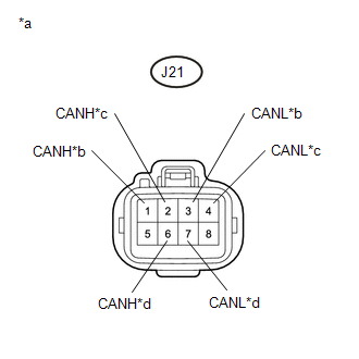
(b) Disconnect the No. 5 CAN junction connector.
|
(c) Measure the resistance according to the value(s) in the table below. Standard Resistance:
|
|
|
Result |
Proceed to |
|---|---|
|
OK |
A |
|
NG (No. 4 CAN junction connector CAN main line) |
B |
|
NG (to No. 6 CAN junction connector CAN main line) |
C |
|
NG (ECU or sensor CAN branch lines) |
D |
| A | |
REPLACE NO. 5 CAN JUNCTION CONNECTOR |
| C | |
REPAIR OR REPLACE CAN MAIN WIRE OR CONNECTOR (NO. 5 CAN JUNCTION CONNECTOR - NO. 6 CAN JUNCTION CONNECTOR) |
| D | |
GO TO STEP 6 |
|
|
4. |
CHECK FOR SHORT IN CAN BUS LINES (NO. 4 CAN JUNCTION CONNECTOR) |
(a) Reconnect the J21 No. 5 CAN junction connector.
(b) Disconnect the No. 4 CAN junction connector.
|
(c) Measure the resistance according to the value(s) in the table below. Standard Resistance:
|
|
|
Result |
Proceed to |
|---|---|
|
OK |
A |
|
NG (Central gateway ECU (network gateway ECU) CAN main line) |
B |
|
NG (to No. 5 CAN junction connector CAN main line) |
C |
|
NG (ECU or sensor CAN branch lines) |
D |
| A | |
REPLACE NO. 4 CAN JUNCTION CONNECTOR |
| C | |
REPAIR OR REPLACE CAN MAIN WIRE OR CONNECTOR (NO. 4 CAN JUNCTION CONNECTOR - NO. 5 CAN JUNCTION TERMINAL) |
| D | |
GO TO STEP 6 |
|
|
5. |
CHECK FOR SHORT IN CAN BUS LINES (NO. 4 CAN JUNCTION CONNECTOR - CENTRAL GATEWAY ECU (NETWORK GATEWAY ECU)) |
(a) Disconnect the N36 central gateway ECU (network gateway ECU) connector.
|
(b) Measure the resistance according to the value(s) in the table below. Standard Resistance:
|
|
| OK | |
REPLACE CENTRAL GATEWAY ECU (NETWORK GATEWAY ECU) |
| NG | |
REPAIR OR REPLACE CAN MAIN BUS LINES OR CONNECTOR (NO. 4 CAN JUNCTION CONNECTOR - CENTRAL GATEWAY ECU (NETWORK GATEWAY ECU)) |
|
6. |
CHECK FOR SHORT IN CAN BUS LINES (ECU, SENSOR) |
|
(a) Reconnect the CAN junction connector. |
|
(b) Disconnect the connector that includes terminals CANH and CANL from the ECU or sensor to which the short circuited CAN branch wire is connected.
(c) Measure the resistance according to the value(s) in the table below.
Standard Resistance:
|
Tester Connection |
Condition |
Specified Condition |
|---|---|---|
|
N36-15 (CA5H) - N36-16 (CA5L) |
Cable disconnected from negative (-) battery terminal |
54 to 69 Ω |
HINT:
If the resistance becomes normal (between 54 and 69 Ω) when the connector is disconnected from the ECU or sensor, there may be a short in the ECU or sensor.
| OK | |
REPLACE ECU OR SENSOR |
| NG | |
REPAIR OR REPLACE HARNESS OR CONNECTOR |
 Open in One Side of Bus 3 Branch Line
DESCRIPTION
When the CAN bus main lines are normal (no open, short to ground, short to +B
or short between lines) and there is an ECU or sensor on the "Communication Bus
Check" screen t ...
 Check Bus 5 Line for Short to +B
DESCRIPTION
There may be a short circuit between one of the CAN bus lines and +B when no
resistance exists between terminal 15 (CA5H) of the central gateway ECU (network
gateway ECU) and terminal ...
Other materials:
Inspection
INSPECTION
PROCEDURE
1. INSPECT RADIATOR CORE SUB-ASSEMBLY
Check the core plate for damage.
Text in Illustration
*1
Core Plate
*2
Radiator Core
If the sides of the core plate groove are deformed, it is impossible
to reassem ...
How To Proceed With Troubleshooting
CAUTION / NOTICE / HINT
HINT:
Use the following procedure to troubleshoot the intuitive parking assist
system.
*: Use the Techstream.
PROCEDURE
1.
VEHICLE BROUGHT TO WORKSHOP
NEXT
...
Speaker Circuit
DESCRIPTION
If there is a short in a speaker circuit, the radio and display receiver
assembly detects it and stops output to the speakers.
Thus sound cannot be heard from the speakers even if there is no malfunction
in the radio and display receiver assembly or speakers.
If a ...
