Toyota Tacoma (2005–2015) Owners Manual: Outside rear view mirrors
Mirror angle can be adjusted.
 Power-adjustable type
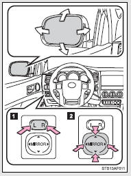
 Select a mirror to adjust.
(L: left or R: right)
 Adjust the mirror up, down, in or
out using the switch.
Adjust the mirror up, down, in or
out using the switch.
Manually adjustable type
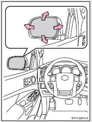
Adjust the mirror up, down, in or out by pushing the mirror surface.
Folding back the mirrors
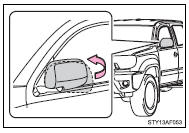
Push backward to fold the mirrors.
■Mirror operating conditions (vehicles with power-adjustable type only)
The engine switch is in the ACC or ON position.
CAUTION
■When driving the vehicle
Observe the following precautions while driving.
Failing to do so may result in loss of control of the vehicle and cause an accident, resulting in death or serious injury.
●Do not adjust the mirrors while driving.
●Do not drive with the mirrors folded back.
●Both the driver and passenger side mirrors must be extended and properly adjusted before driving.
NOTICE
■If ice should jam the mirror
Do not operate the control or scrape the mirror face. Use a spray de-icer to free the mirror.
 Anti-glare inside rear view mirror
Glare from the headlights of vehicles behind can be reduced by using the following
functions.
Manual anti-glare inside rear view
mirror
Normal position
Anti-glare position
Auto anti-glare ...

Other materials:
Removal
REMOVAL
PROCEDURE
1. PRECAUTION
NOTICE:
After turning the ignition switch off, waiting time may be required before disconnecting
the cable from the negative (-) battery terminal. Therefore, make sure to read the
disconnecting the cable from the negative (-) battery terminal notices before pr ...
Terminals Of Ecu
TERMINALS OF ECU
1. CHECK ENGINE SWITCH
(a) Measure the resistance and voltage according to the value(s) in the table
below.
Terminal No. (Symbol)
Input/Output
Wiring Color
Terminal Description
Condition
Specified Condition
...
Installation
INSTALLATION
CAUTION / NOTICE / HINT
HINT:
Perform "Inspection After Repairs" after replacing the engine assembly, cylinder
head sub-assembly, camshaft, No. 2 camshaft, No. 3 camshaft sub-assembly, No. 4
camshaft sub-assembly, camshaft timing gear assembly, camshaft timing exhaust g ...
