Toyota Tacoma (2015-2018) Service Manual: Inspection
INSPECTION
PROCEDURE
1. INSPECT FUEL INJECTOR ASSEMBLY
(a) Measure the resistance according to the value(s) in the table below.
Standard Resistance:
|
Tester Connection |
Condition |
Specified Condition |
|---|---|---|
|
1 - 2 |
20┬░C (68┬░F) |
11.6 to 12.4 ╬й |
If the resistance is not as specified, replace the fuel injector assembly.
(b) Inspect the injection volume.
CAUTION:
This test involves high-pressure fuel and electricity. Take all precautions regarding safe handling of both the fuel and the electricity. Perform this test in a safe area, and avoid any sparks or flames. Do not smoke.
|
(c) Disengage the 2 claws and remove the No. 2 fuel pipe clamp. |
|

|
(d) Remove the No. 1 fuel pipe clamp. |
|
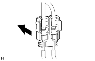
(e) Disconnect the fuel tube sub-assembly (engine compartment right side) (See
page .gif) ).
).
|
(f) Connect SST to the fuel pipe (vehicle side). Text in Illustration
SST: 09268-31014 09268-41500 09268-41700 95336-08070 |
|
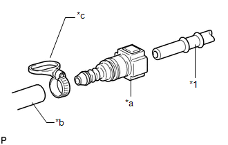
|
(g) Install the O-ring to the fuel injector. Text in Illustration
|
|
(h) Install SST and a tube to the fuel injector.
SST: 09268-31014
09268-41600
09268-41300
09268-41700
95336-08070
|
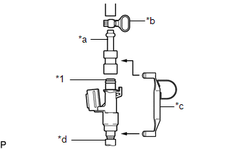
(i) Pass SST (tie band) through the loop on the handle of SST (clamp) to secure SST (clamp) to SST (adapter). Text in Illustration
SST: 09268-31014 09268-41800 NOTICE:
HINT: When removing SST (tie band), disengage the lock. |
|
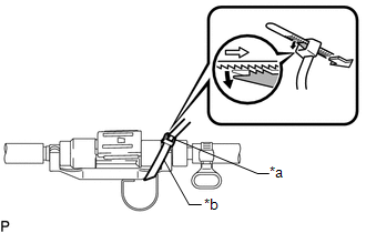
(j) Check that SST (clamp) and SST (adapter) cannot be easily separated.
(k) Install a vinyl tube to the fuel injector assembly.
NOTICE:
Install a suitable vinyl tube onto the fuel injector assembly to contain the gasoline spray.
(l) Set the fuel injector assembly in a graduated cylinder.
(m) Operate the fuel pump (See page
).
|
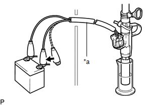
(n) Connect SST (EFI inspection wire I) to the fuel injector assembly and battery for 15 seconds, and measure the injection volume with the graduated cylinder. Test each fuel injector assembly 2 or 3 times. Text in Illustration
SST: 09842-30090 Standard injection volume: 67 to 81 cc (4.1 to 4.9 cu.in.) per 15 seconds Difference between each injector: 14 cc (0.9 cu.in.) or less NOTICE:
If the injection volume is not as specified, replace the fuel injector assembly. |
|
(o) Check for leakage.
(1) Disconnect the tester probes of SST (EFI inspection wire I) from the battery and check for fuel leaks from the fuel injector assembly.
Standard fuel drop:
1 drop or less in 20 minutes
If there is excessive leakage, replace the fuel injector assembly.
 Components
COMPONENTS
ILLUSTRATION
...
 Removal
REMOVAL
PROCEDURE
1. REMOVE INTAKE AIR SURGE TANK ASSEMBLY
(See page )
2. DISCONNECT NO. 2 FUEL TUBE SUB-ASSEMBLY
(a) Disengage the 2 clamps.
...
Other materials:
System Diagram
SYSTEM DIAGRAM
Transmitting ECU
(Transmitter)
Receiving ECU
Signal
Communication Method
Airbag Sensor Assembly
ECM
Crash detection signal
CAN
Airbag Sensor Assembly
Com ...
Front Passenger Side Door ECU Communication Stop (B2322)
DESCRIPTION
This DTC is stored when LIN communication between the front power window regulator
motor assembly RH and main body ECU (multiplex network body ECU) stops for 10 seconds
or more.
DTC No.
DTC Detection Condition
Trouble Area
B2322
...
Symbols used in illustrations
The symbol of a circle with a slash
through it means тАЬDo notтАЭ, тАЬDo not do thisтАЭ, or тАЬDo not let this happenтАЭ.
Arrows indicating operations
Indicates the action (pushing, turning,
etc.) used to operate switches and other devices.
Indicates the outcome of an operation
(e.g. a ...
