Toyota Tacoma (2015-2018) Service Manual: Parts Location
PARTS LOCATION
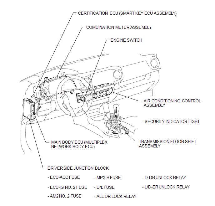
ILLUSTRATION
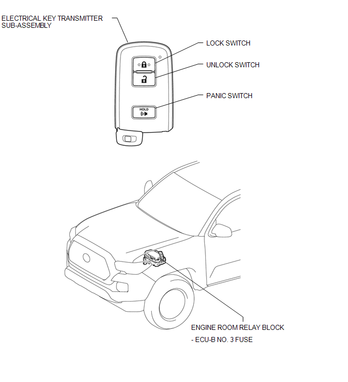
ILLUSTRATION
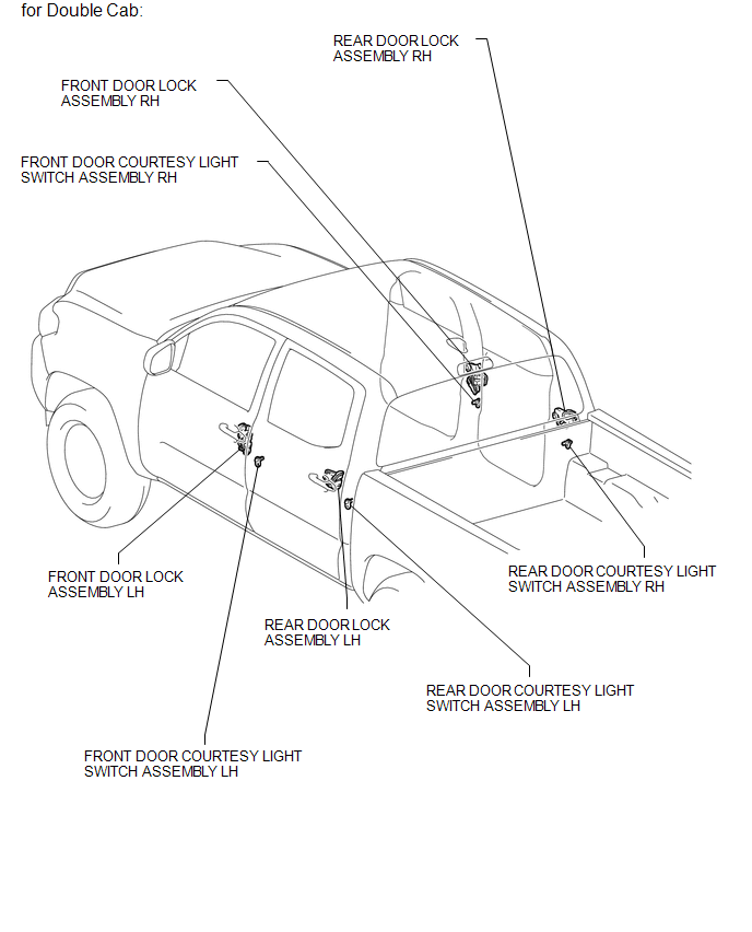
ILLUSTRATION
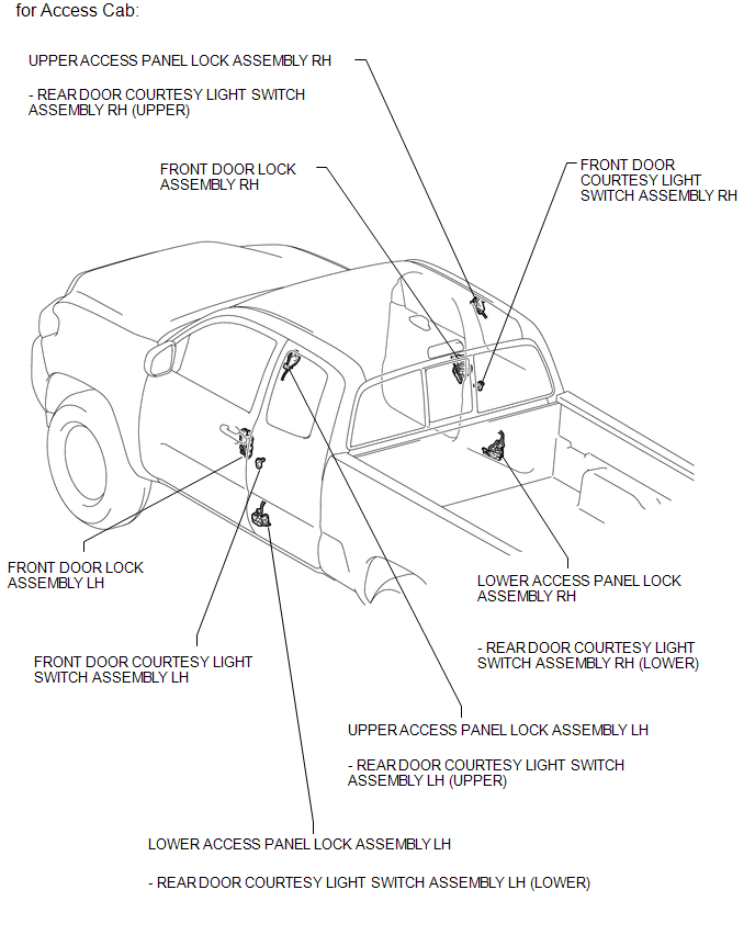
ILLUSTRATION
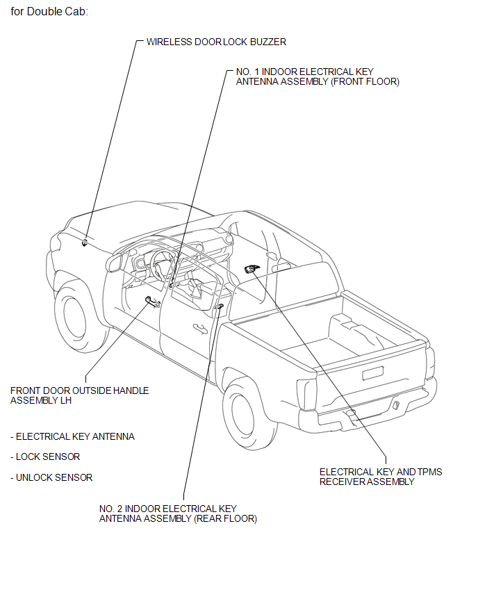
ILLUSTRATION
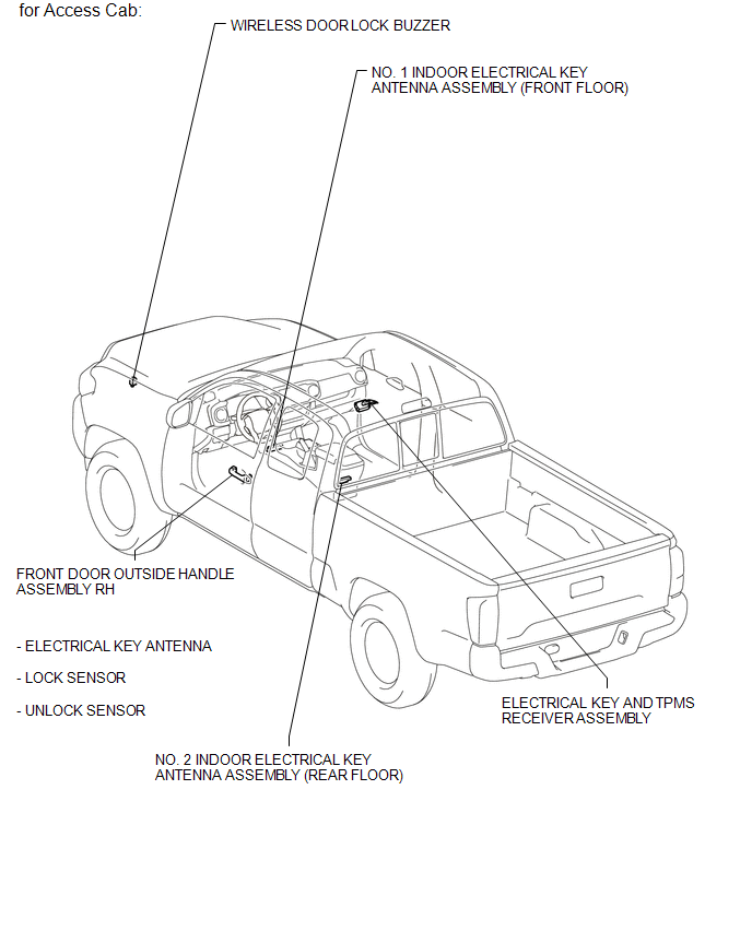
ILLUSTRATION
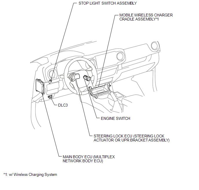
ILLUSTRATION

 Precaution
PRECAUTION
1. CAUTION REGARDING INTERFERENCE WITH ELECTRONIC DEVICES
CAUTION:
People with implantable cardiac pacemakers, cardiac resynchronization
therapy-pacemakers or implantable car ...
Other materials:
Disassembly
DISASSEMBLY
PROCEDURE
1. REMOVE PRESSURE RELIEF VALVE
(a) Remove the pressure relief valve and O-ring.
2. REMOVE MAGNET CLUTCH ASSEMBLY
(a) Secure the cooler compressor assembly in a vise between aluminum plates.
(b) Using SST, hold the magnet clutch hub.
SST: 09985-00260
(c) Remove the ...
Air Inlet Damper Position Sensor Circuit (B1432/32)
DESCRIPTION
This sensor detects the position of the air inlet damper and sends the appropriate
signals to the air conditioning amplifier assembly. The position sensor is built
into the No. 1 air conditioning servo assembly (fresh/recirculation damper).
DTC No.
DTC Detecti ...
Pressure Control Solenoid "C" Electrical (Shift Solenoid Valve SL3) (P0798)
DESCRIPTION
Changing from 1st to 6th is performed by the ECM turning shift solenoid valves
SL1, SL2, SL3 and SL4 on and off. If an open or short circuit occurs in any of the
shift solenoid valves, the ECM controls the remaining normal shift solenoid valves
to allow the vehicle to be operated ...
