Toyota Tacoma (2015-2018) Service Manual: Brake Warning Light Remains ON
DESCRIPTION
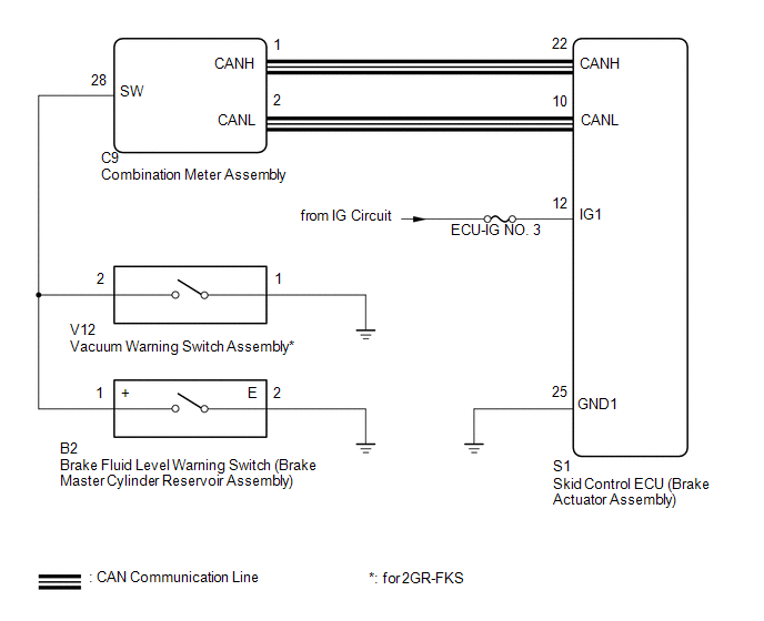
The skid control ECU (brake actuator assembly) is connected to the combination meter assembly via CAN communication.
If any of the following is detected, the brake warning light remains on:
- The skid control ECU (brake actuator assembly) connector is disconnected from the skid control ECU (brake actuator assembly).
- The brake fluid level is insufficient.
- EBD operation is not possible.
- The vacuum inside the brake booster decreases.*
- *: for 2GR-FKS
WIRING DIAGRAM
CAUTION / NOTICE / HINT
NOTICE:
- When replacing the skid control ECU (brake actuator assembly), perform
zero point calibration and store system information (See page
.gif) ).
).
- Inspect the fuses for circuits related to this system before performing the following inspection procedure.
PROCEDURE
|
1. |
CHECK CAN COMMUNICATION SYSTEM |
(a) Check if CAN communication system DTCs are output (See page
).
|
Result |
Proceed to |
|---|---|
|
DTC is not output |
A |
|
DTC is output |
B |
| B | .gif) |
CHECK CAN COMMUNICATION SYSTEM |
|
.gif)
|
2. |
CHECK IF BRAKE ACTUATOR ASSEMBLY CONNECTOR IS SECURELY CONNECTED |
(a) Check if the skid control ECU (brake actuator assembly) connector is securely connected.
OK:
The connector is securely connected.
| NG | |
CONNECT CONNECTOR TO BRAKE ACTUATOR ASSEMBLY CORRECTLY |
|
|
3. |
INSPECT BATTERY |
(a) Check the battery voltage.
Standard voltage:
11 to 14 V
| NG | |
CHECK OR REPLACE CHARGING SYSTEM OR BATTERY |
|
|
4. |
CHECK TERMINAL VOLTAGE (IG1 TERMINAL) |
|
(a) Disconnect the skid control ECU (brake actuator assembly) connector. |
|
.png)
(b) Turn the ignition switch to ON.
(c) Measure the voltage according to the value(s) in the table below.
Standard Voltage:
|
Tester Connection |
Switch Condition |
Specified Condition |
|---|---|---|
|
S1-12 (IG1) - Body ground |
Ignition switch ON |
11 to 14 V |
|
*a |
Front view of wire harness connector (to Skid Control ECU [Brake Actuator Assembly]) |
| NG | |
REPAIR OR REPLACE HARNESS OR CONNECTOR (IG1 CIRCUIT) |
|
|
5. |
CHECK HARNESS AND CONNECTOR (GND1 TERMINAL) |
(a) Turn the ignition switch off.
|
(b) Measure the resistance according to the value(s) in the table below. Standard Resistance:
|
|
.png)
| NG | |
REPAIR OR REPLACE HARNESS OR CONNECTOR (GND1 CIRCUIT) |
|
|
6. |
INSPECT BRAKE MASTER CYLINDER RESERVOIR ASSEMBLY |
|
(a) Turn the ignition switch off. |
|
(b) Remove the reservoir filler cap and strainer.
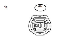
(c) Disconnect the A6 brake fluid level warning switch (brake master cylinder reservoir assembly) connector.
(d) Measure the resistance according to the value(s) in the table below.
HINT:
A float is located inside the reservoir. Its position can be changed by increasing or decreasing the level of brake fluid.
Standard Resistance:
|
Tester Connection |
Switch Condition |
Specified Condition |
|---|---|---|
|
1 - 2 |
Switch off (Float up) |
10 kΩ or higher |
|
Switch on (Float down) |
Below 1 Ω |
|
*a |
Component without harness connected (Brake Fluid Level Warning Switch [Brake Master Cylinder Reservoir Assembly]) |
HINT:
If there is no problem after finishing the above check, adjust the brake fluid level to the MAX level.
| NG | |
REPLACE BRAKE MASTER CYLINDER RESERVOIR ASSEMBLY |
|
|
7. |
CHECK HARNESS AND CONNECTOR (COMBINATION METER ASSEMBLY - BRAKE MASTER CYLINDER RESERVOIR ASSEMBLY) |
(a) Disconnect the C9 combination meter assembly connector.
(b) Measure the resistance according to the value(s) in the table below.
Standard Resistance:
|
Tester Connection |
Condition |
Specified Condition |
|---|---|---|
|
C9-28 (SW) - B2-1 (+) |
Always |
Below 1 Ω |
|
B2-2 (E) - Body ground |
Always |
10 kΩ or higher |
|
C9-28 (SW) or B2-1 (+) - Body ground |
Always |
10 kΩ or higher |
|
Result |
Proceed to |
|---|---|
|
OK (for 2GR-FKS) |
A |
|
OK (for 2TR-FE) |
B |
|
NG |
C |
| B | |
GO TO STEP 10 |
| C | |
REPAIR OR REPLACE HARNESS OR CONNECTOR |
|
|
8. |
INSPECT VACUUM WARNING SWITCH ASSEMBLY |
(a) Remove the vacuum warning switch assembly (See page
).
(b) Inspect the vacuum warning switch assembly (See page
).
OK:
The vacuum warning switch assembly is normal.
| NG | |
REPLACE VACUUM WARNING SWITCH ASSEMBLY |
|
|
9. |
CHECK HARNESS AND CONNECTOR (BRAKE WARNING LIGHT CIRCUIT) |
(a) Measure the resistance according to the value(s) in the table below.
Standard Resistance:
|
Tester Connection |
Condition |
Specified Condition |
|---|---|---|
|
C9-28 (SW) - V12-2 |
Always |
Below 1 Ω |
|
V12-1 - Body ground |
Always |
Below 1 Ω |
|
C9-9 (SW) or V12-2 - Body ground |
Always |
10 kΩ or higher |
| NG | |
REPAIR OR REPLACE HARNESS OR CONNECTOR |
|
|
10. |
READ VALUE USING TECHSTREAM (BRAKE WARNING LIGHT) |
(a) Reinstall the reservoir filler cap and strainer.
(b) for 2GR-FKS
Reinstall the vacuum warning switch assembly.
(c) Reconnect the C9 combination meter assembly connector, S1 skid control ECU (brake actuator assembly) connector and the A6 brake fluid level warning switch (brake master cylinder reservoir assembly) connector.
(d) for 2GR-FKS
Reconnect the V12 vacuum warning switch assembly connector.
(e) Connect the Techstream to the DLC3.
(f) Turn the ignition switch to ON.
(g) Turn the Techstream on.
(h) Enter the following menus: Chassis / ABS/VSC/TRAC / Data List.
(i) According to the display on the Techstream, read the Data List.
ABS/VSC/TRAC|
Tester Display |
Measurement Item |
Range |
Normal Condition |
Diagnostic Note |
|---|---|---|---|---|
|
Brake Warning Light |
Brake warning light |
OFF or ON |
OFF: Warning light off ON: Warning light on |
- |
(j) Check the Techstream display condition of the brake warning light.
Result|
Result |
Proceed to |
|---|---|
|
Display of the Data List remains OFF |
A |
|
Display of the Data List remains ON |
B |
| A | |
INSPECT METER / GAUGE SYSTEM |
| B | |
REPLACE BRAKE ACTUATOR ASSEMBLY |
 ABS Warning Light Remains ON
DESCRIPTION
The skid control ECU (brake actuator assembly) is connected to the combination
meter assembly via CAN communication.
If any of the following is detected, the ABS warning light remains ...
 Brake Warning Light does not Come ON
DESCRIPTION
The skid control ECU (brake actuator assembly) is connected to the combination
meter assembly via CAN communication.
WIRING DIAGRAM
Refer to Brake Warning Light Remains ON (See page
...
Other materials:
Diagnostic Trouble Code Chart
DIAGNOSTIC TROUBLE CODE CHART
HINT:
If a trouble code is stored during the DTC check, inspect the trouble areas listed
for that code. For details of the code, refer to "See page" below.
Transponder Key ECU Assembly
DTC Code
Detection Item
See page
...
Tires
Replace or rotate tires in accordance with maintenance schedules and treadwear.
■ Checking tire
1. New tread
2. Treadwear indicator
3. Worn tread
The location of treadwear indicators is shown by the “TWI” or “
” marks, etc., molded on the sidewall of each tire.
Check spare ti ...
Diagnostic Trouble Code Chart
DIAGNOSTIC TROUBLE CODE CHART
HINT:
If a trouble code is displayed during the DTC check, inspect the trouble area
for that code. For details of each code, refer to the relevant page listed under
respective "See page" in the DTC chart.
Tire Pressure Warning ECU and Receiver
...
