Toyota Tacoma (2015-2018) Service Manual: Main Body ECU Communication Stop Mode
DESCRIPTION
|
Detection Item |
Symptom |
Trouble Area |
|---|---|---|
|
Main Body ECU Communication Stop Mode |
Either condition is met:
|
|
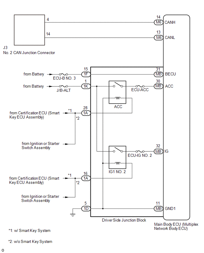
WIRING DIAGRAM
CAUTION / NOTICE / HINT
CAUTION:
When performing the confirmation driving pattern, obey all speed limits and traffic laws.
NOTICE:
- Because the order of diagnosis is important to allow correct diagnosis,
make sure to begin troubleshooting using How to Proceed with Troubleshooting
when CAN communication system related DTCs are output.
Click here
.gif)
- Before measuring the resistance of the CAN bus, turn the ignition switch off and leave the vehicle for 1 minute or more without operating the key or any switches, or opening or closing the doors. After that, disconnect the cable from the negative (-) battery terminal and leave the vehicle for 1 minute or more before measuring the resistance.
- After turning the ignition switch off, waiting time may be required
before disconnecting the cable from the negative (-) battery terminal. Therefore,
make sure to read the disconnecting the cable from the negative (-) battery
terminal notices before proceeding with work.
Click here
- Some parts must be initialized and set when replacing or removing and
installing parts.
Click here
- After performing repairs, perform the DTC check procedure and confirm
that the DTCs are not output again.
DTC check procedure: Turn the ignition switch to ON and wait for 1 minute or more. Then operate the suspected malfunctioning system and drive the vehicle at 60 km/h (37 mph) or more for 5 minutes or more.
- After the repair, perform the CAN bus check and check that all the ECUs
and sensors connected to the CAN communication system are displayed as normal.
Click here
- Inspect the fuses for circuits related to this system before performing the following procedure.
- If the main body ECU (multiplex network body ECU) is replaced, refer
to Registration.
Click here
HINT:
- Before disconnecting related connectors for inspection, push in on each connector body to check that the connector is not loose or disconnected.
- When a connector is disconnected, check that the terminals and connector body are not cracked, deformed or corroded.
PROCEDURE
|
1. |
CHECK FOR OPEN IN CAN BUS LINES (MAIN BODY ECU (MULTIPLEX NETWORK BODY ECU) BRANCH LINE) |
(a) Disconnect the cable from the negative (-) battery terminal.
|
(b) Disconnect the main body ECU (multiplex network body ECU) connector. |
|
(c) Measure the resistance according to the value(s) in the table below.
Standard Resistance:
|
Tester Connection |
Condition |
Specified Condition |
|---|---|---|
|
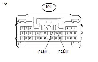
M6-14 (CANH) - M6-13 (CANL) |
Cable disconnected from negative (-) battery terminal |
54 to 69 Ω |
|
*a |
Front view of wire harness connector (to Main Body ECU (Multiplex Network Body ECU)) |
| NG | .gif) |
REPAIR OR REPLACE CAN BRANCH LINE OR CONNECTOR (MAIN BODY ECU (MULTIPLEX NETWORK BODY ECU)) |
|
.gif)
|
2. |
CHECK HARNESS AND CONNECTOR (POWER SOURCE CIRCUIT) |
|
(a) Remove the main body ECU (multiplex network body ECU). Click here |
|
(b) Measure the resistance according to the value(s) in the table below.
Standard Resistance:
|
Tester Connection |
Condition |
Specified Condition |
|---|---|---|
|
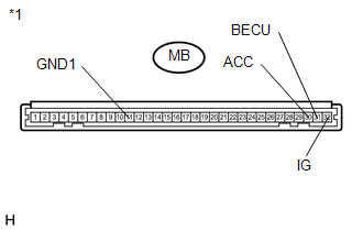
MB-11 (GND1) - Body ground |
Cable disconnected from negative (-) battery terminal |
Below 1 Ω |
(c) Connect the cable to the negative (-) battery terminal.
(d) Measure the voltage according to the value(s) in the table below.
Standard Voltage:
|
Tester Connection |
Switch Condition |
Specified Condition |
|---|---|---|
|
MB-30 (ACC) - Body ground |
Ignition switch ACC |
11 to 14 V |
|
MB-31 (BECU) - Body ground |
Always |
11 to 14 V |
|
MB-32 (IG) - Body ground |
Ignition switch ON |
11 to 14 V |
|
*1 |
Driver Side Junction Block |
|
Result |
Proceed to |
|---|---|
|
OK |
A |
|
NG (for BECU circuit) |
B |
|
NG (for ACC circuit) |
C |
|
NG (for IG circuit) |
D |
|
NG (for GND1 circuit) |
E |
| A | |
REPLACE MAIN BODY ECU (MULTIPLEX NETWORK BODY ECU) |
| C | |
GO TO LIGHTING SYSTEM (ACC SIGNAL CIRCUIT) |
| D | |
GO TO LIGHTING SYSTEM (IG SIGNAL CIRCUIT) |
| E | |
GO TO STEP 4 |
|
|
3. |
CHECK HARNESS AND CONNECTOR (BECU CIRCUIT) |
|
(a) Disconnect the driver side junction block connector. |
|
(b) Measure the voltage according to the value(s) in the table below.
Standard Voltage:
|
Tester Connection |
Condition |
Specified Condition |
|---|---|---|
|
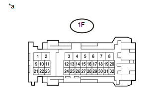
1F-15 - Body ground |
Always |
11 to 14 V |
|
*a |
Front view of wire harness connector (to Driver Side Junction Block) |
| OK | |
REPLACE DRIVER SIDE JUNCTION BLOCK |
| NG | |
REPAIR OR REPLACE HARNESS OR CONNECTOR (BECU CIRCUIT) |
|
4. |
CHECK HARNESS AND CONNECTOR (GND1 CIRCUIT) |
|
(a) Disconnect the driver side junction block connector. |
|
(b) Measure the resistance according to the value(s) in the table below.
Standard Resistance:
|
Tester Connection |
Condition |
Specified Condition |
|---|---|---|
|
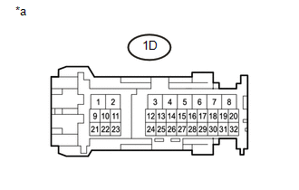
1D-5 - Body ground |
Always |
Below 1 Ω |
|
*a |
Front view of wire harness connector (to Driver Side Junction Block) |
| OK | |
REPLACE DRIVER SIDE JUNCTION BLOCK |
| NG | |
REPAIR OR REPLACE HARNESS OR CONNECTOR (GND1 CIRCUIT) |
 ECM Communication Stop Mode
DESCRIPTION
Detection Item
Symptom
Trouble Area
ECM Communication Stop Mode
Either condition is met:
Communication stop for ...
 Steering Angle Sensor Communication Stop Mode
DESCRIPTION
Detection Item
Symptom
Trouble Area
Steering Angle Sensor Communication Stop Mode
Either condition is met:
Commu ...
Other materials:
Abbreviations Used In Manual
ABBREVIATIONS USED IN MANUAL
Abbreviations
Meaning
ABS
Anti-Lock Brake System
A/C
Air Conditioner
AC
Alternating Current
ACC
Accessory
ACIS
...
Removal
REMOVAL
CAUTION / NOTICE / HINT
PROCEDURE
1. PRECAUTION
CAUTION:
Be sure to read Precaution thoroughly before servicing (See page
).
NOTICE:
After turning the ignition switch off, waiting time may be required before disconnecting
the cable from the negative (-) battery terminal. Therefore ...
Operation Check
OPERATION CHECK
1. CHECK NAVIGATION SYSTEM NORMAL CONDITION
(a) If the symptom is applicable to any of the following, it is intended behavior,
and not a malfunction.
Symptom
Answer
A longer route than expected is chosen.
Depending on the road co ...
