Toyota Tacoma (2015-2018) Service Manual: Transponder Key Amplifier
Components
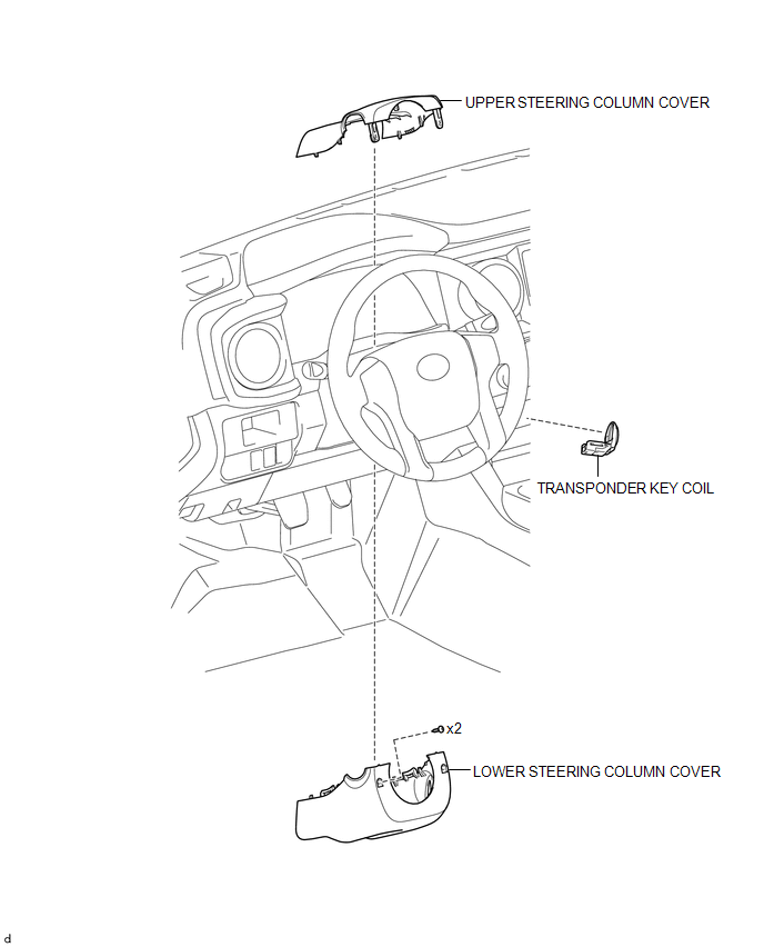
COMPONENTS
ILLUSTRATION
Installation
INSTALLATION
PROCEDURE
1. INSTALL TRANSPONDER KEY COIL
|
(a) Engage the 2 claws to install the transponder key coil. |
|
(b) Connect the connector.
2. INSTALL UPPER STEERING COLUMN COVER
(See page .gif) )
)
3. INSTALL LOWER STEERING COLUMN COVER
(See page
)
Removal
REMOVAL
PROCEDURE
1. REMOVE LOWER STEERING COLUMN COVER
(See page .gif) )
)
2. REMOVE UPPER STEERING COLUMN COVER
(See page
)
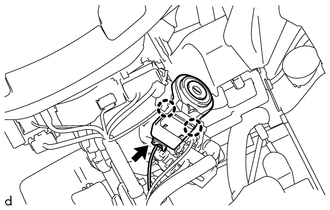
3. REMOVE TRANSPONDER KEY COIL
|
(a) Disconnect the connector. |
|
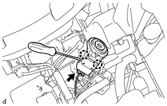
(b) Using a screwdriver with its tip wrapped in protective tape, disengage the 2 claws to remove the transponder key coil.
Text in Illustration|
*a |
Protective Tape |
 Security Indicator Light Does not Blink
DESCRIPTION
The transponder key ECU assembly blinks the security indicator light
when the immobiliser is set (no key is in the ignition key cylinder).
w/ Theft Deterrent System:
...
 Transponder Key Ecu
Components
COMPONENTS
ILLUSTRATION
Installation
INSTALLATION
PROCEDURE
1. INSTALL TRANSPONDER KEY ECU
(a) Engage the 2 guides to move the transponder key ECU in the direction
...
Other materials:
Occupant Classification ECU Malfunction (B1795)
DESCRIPTION
DTC B1795 is set when a malfunction is detected in the occupant detection ECU.
Troubleshoot DTC B1771 first when both DTCs B1771 and B1795 are present.
DTC No.
DTC Detections Conditions
Trouble Areas
B1795
Occupant detection ...
Inspection
INSPECTION
PROCEDURE
1. INSPECT CAMSHAFT TIMING OIL CONTROL SOLENOID ASSEMBLY
(a) Check the operation.
(1) Apply battery voltage between the terminals and check that the plunger
operates.
Text in Illustration
*a
Component without harness con ...
On-vehicle Inspection
ON-VEHICLE INSPECTION
PROCEDURE
1. INSPECT FRONT SEAT AIRBAG ASSEMBLY LH (for Vehicle not Involved in Collision)
(a) Perform a diagnostic system check (See page
).
(b) With the front seat airbag assembly LH installed on the vehicle, perfor ...
