Toyota Tacoma (2015-2018) Service Manual: Brake Switch "A" Signal Compare Failure (P057162)
DESCRIPTION
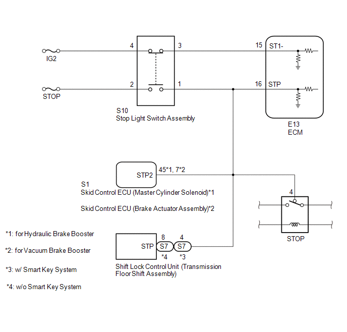
When the brake pedal is depressed, the stop light switch assembly sends a signal to the ECM. When the ECM receives this signal, it cancels the dynamic radar cruise control. The fail-safe function operates to enable normal driving even if there is a malfunction in the stop light signal circuit. The cancellation condition occurs when voltage is applied to terminal STP. When the brake is applied, voltage is normally applied to terminal STP of the ECM through the STOP fuse and the stop light switch assembly, and the ECM turns the dynamic radar cruise control system off.
|
DTC No. |
Detection Item |
DTC Detection Condition |
Trouble Area |
MIL |
|---|---|---|---|---|
|
P057162 |
Brake Switch "A" Signal Compare Failure |
While the ignition switch is ON and the dynamic radar cruise control system is operating, voltage of STP terminal and that of ST1- terminal of ECM are less than 1 V for approximately 0.5 seconds or more. |
|
Does not come on |
WIRING DIAGRAM
CAUTION / NOTICE / HINT
NOTICE:
- Inspect the fuses for circuits related to this system before performing the following procedure.
- Before replacing the ECM, refer to Registration.
w/o Smart Key System: Click here
.gif)
w/ Smart Key System: Click here
PROCEDURE
|
1. |
CHECK HARNESS AND CONNECTOR (STOP LIGHT SWITCH ASSEMBLY - BATTERY AND BODY GROUND) |
|
(a) Disconnect the stop light switch assembly connector. |
|
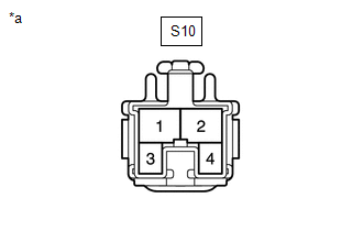
(b) Measure the voltage according to the value(s) in the table below.
Standard Voltage:
|
Tester Connection |
Condition |
Specified Condition |
|---|---|---|
|
S10-2 - Body ground |
Always |
11 to 14 V |
|
S10-4 - Body ground |
Ignition switch to ON |
11 to 14 V |
|
S10-4 - Body ground |
Ignition switch off |
Below 1 V |
| NG | .gif) |
REPAIR OR REPLACE HARNESS OR CONNECTOR |
|
.gif)
|
2. |
INSPECT STOP LIGHT SWITCH ASSEMBLY |
(a) Remove the stop light switch assembly.
Click here
(b) Inspect the stop light switch assembly.
Click here
| NG | |
REPLACE STOP LIGHT SWITCH ASSEMBLY |
|
|
3. |
CHECK HARNESS AND CONNECTOR (ECM - STOP LIGHT SWITCH ASSEMBLY) |
(a) Disconnect the E13 ECM connector.
(b) Disconnect the S10 stop light switch assembly connector.
(c) Disconnect the S1 skid control ECU (master cylinder solenoid)*1 or skid control ECU (brake actuator assembly)*2 connector.
- *1: for Hydraulic Brake Booster
- *2: for Vacuum Brake Booster
(d) Disconnect the S7 shift lock control unit connector.
(e) Remove the STOP relay from the engine room relay block.
(f) Measure the resistance according to the value(s) in the table below.
Standard Resistance:
|
Tester Connection |
Condition |
Specified Condition |
|---|---|---|
|
E13-15 (ST1-) - S10-3 |
Always |
Below 1 Ω |
|
E13-16 (STP) - S10-1 |
Always |
Below 1 Ω |
|
E13-15 (ST1-) or S10-3 - Body ground |
Always |
10 kΩ or higher |
|
E13-16 (STP) or S10-1 - Body ground |
Always |
10 kΩ or higher |
| OK | |
REPLACE ECM |
| NG | |
REPAIR OR REPLACE HARNESS OR CONNECTOR |
 Communication Error from VSC to ECM Invalid Serial Data Received (P163081)
DESCRIPTION
The skid control ECU (master cylinder solenoid)*1 or skid control ECU (brake
actuator assembly)*2 sends signals such as cruise control cancel signals and brake
demand response signals ...
 Cruise Control System Internal Failure (P057504,P057549)
DESCRIPTION
This DTC is stored when there is a malfunction in the ECM.
DTC No.
Detection Item
DTC Detection Condition
Trouble Area
MIL
...
Other materials:
Precaution
PRECAUTION
1. IGNITION SWITCH EXPRESSION
HINT:
The type of ignition switch used on this model differs depending on the specifications
of the vehicle. The expressions listed in the table below are used in this section.
Expression
Ignition Switch (Position)
Engin ...
What to do if...
■ Instrument cluster
■ Center panel
■Warning lights
*1: Slip indicator comes on.
*2: The indicator flashes to indicate a malfunction.
GAS STATION INFORMATION
...
Engine does not Start but Initial Combustion Occurs
DESCRIPTION
If the key ID codes of the key and transponder key ECU assembly match, the engine
immobiliser system is unset and the engine start permission signal is sent to the
ECM. When the ID codes of the transponder key ECU assembly and ECM match, the engine
starts.
WIRING DIAGRAM
CAUTI ...
