Toyota Tacoma (2015-2018) Service Manual: Removal
REMOVAL
PROCEDURE
1. REMOVE MILLIMETER WAVE RADAR WIRE
|
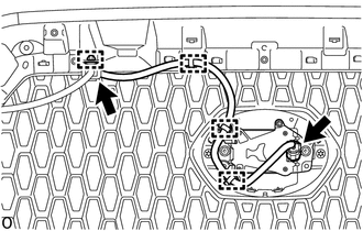
(a) for Type A: (1) Disconnect the 2 connectors. (2) Using a clip remover, disengage the 4 clamps to remove the millimeter wave radar wire. |
|
|
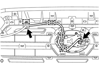
(b) for Type B: (1) Disconnect the 2 connectors. (2) Using a clip remover, disengage the 4 clamps to remove the millimeter wave radar wire. |
|
|
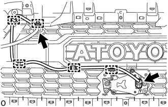
(c) for Type C: (1) Disconnect the 2 connectors. (2) Using a clip remover, disengage the 5 clamps to remove the millimeter wave radar wire. |
|
2. REMOVE MILLIMETER WAVE RADAR SENSOR ASSEMBLY
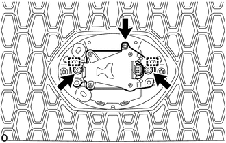
NOTICE:
Do not reuse the millimeter wave radar sensor assembly if it has been dropped or subjected to a severe impact.
|
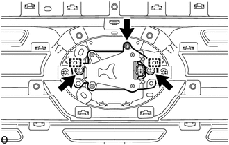
(a) for Type A: (1) Remove the 2 bolts and screw. (2) Disengage the 2 guides to remove the millimeter wave radar sensor assembly. |
|
|
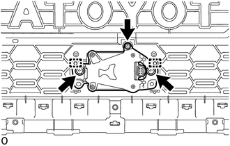
(b) for Type B: (1) Remove the 2 bolts and screw. (2) Disengage the 2 guides to remove the millimeter wave radar sensor assembly. |
|
|
(c) for Type C: (1) Remove the 2 bolts and screw. (2) Disengage the 2 guides to remove the millimeter wave radar sensor assembly. |
|
 Adjustment
ADJUSTMENT
CAUTION / NOTICE / HINT
CAUTION:
Radiofrequency radiation exposure information:
This equipment complies with FCC radiation exposure limits set forth
for an uncontrolled envir ...
 Installation
INSTALLATION
CAUTION / NOTICE / HINT
NOTICE:
If the millimeter wave radar sensor assembly has been struck or dropped, replace
the millimeter wave radar sensor assembly with a new one.
PROCEDURE
...
Other materials:
Diagnostic Trouble Code Chart
DIAGNOSTIC TROUBLE CODE CHART
HINT:
If a trouble code is displayed during the DTC check, inspect the trouble areas
listed for that code. For details of the code, refer to the "See page" below.
Seat Heater System
DTC Code
Detection Item
See page
...
Entry Interior Alarm does not Sound
DESCRIPTION
The smart key system (for Entry Function) uses the buzzer in the combination
meter assembly to perform various vehicle interior warnings. When the conditions
of each warning are met, the certification ECU (smart key ECU assembly) sends a
buzzer activation request signal to the com ...
Pressure Control Solenoid "A" Performance (Shift Solenoid Valve SL1) (P0746)
SYSTEM DESCRIPTION
The ECM uses the vehicle speed signal and signals from the transmission revolution
sensors (NT, SP2) to detect the actual gear (1st, 2nd, 3rd, 4th, 5th or 6th gear).
The ECM compares the actual gear with the shift schedule in the ECM memory to
detect mechanical problems of t ...
