Toyota Tacoma (2015-2018) Service Manual: Security Indicator Light Does not Blink
DESCRIPTION
- The transponder key ECU assembly blinks the security indicator light when the immobiliser is set (no key is in the ignition key cylinder).
- w/ Theft Deterrent System:
The main body ECU (multiplex network body ECU) blinks the security indicator light when the theft deterrent system is in the arming preparation state or alarm sounding state.
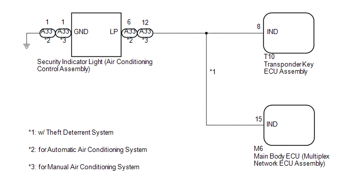
WIRING DIAGRAM
CAUTION / NOTICE / HINT
NOTICE:
If the transponder key ECU assembly is replaced, refer to Registration (See page
.gif) ).
).
PROCEDURE
|
1. |
SYSTEM CHECK |
(a) Check the vehicle specification.
Result|
Result |
Proceed to |
|---|---|
|
w/o Theft Deterrent System |
A |
|
w/ Theft Deterrent System |
B |
| B | .gif) |
GO TO STEP 5 |
|
.gif)
|
2. |
PERFORM ACTIVE TEST USING TECHSTREAM |
(a) Connect the Techstream to the DLC3.
(b) Turn the ignition switch to ON.
(c) Turn the Techstream on.
(d) Enter the following menus: Body Electrical / Immobiliser / Active Test.
(e) Perform the Active Test according to the display on the Techstream.
Immobiliser|
Tester Display |
Test Part |
Control Range |
Diagnostic Note |
|---|---|---|---|
|
Security Indicator |
Security indicator light |
ON/OFF |
- |
OK:
The security indicator light operates normally by using the Active Test.
| OK | |
REPLACE TRANSPONDER KEY ECU ASSEMBLY |
|
|
3. |
CHECK HARNESS AND CONNECTOR (AIR CONDITIONING CONTROL ASSEMBLY - TRANSPONDER KEY ECU ASSEMBLY) |
(a) Disconnect the A33 security indicator light (air conditioning control assembly) connector.
(b) Disconnect the T10 transponder key ECU assembly connector.
(c) Measure the resistance according to the value(s) in the table below.
Standard Resistance:
|
Tester Connection |
Condition |
Specified Condition |
|---|---|---|
|
T10-8 (IND) - A33-6 (LP)*1 |
Always |
Below 1 Ω |
|
T10-8 (IND) or A33-6 (LP) - Body ground*1 |
Always |
10 kΩ or higher |
|
A33-1 (GND) - Body ground |
Always |
Below 1 Ω |
|
T10-8 (IND) - A33-12 (LP)*2 |
Always |
Below 1 Ω |
|
T10-8 (IND) or A33-12 (LP) - Body ground*2 |
Always |
10 kΩ or higher |
- *1: for Automatic Air Conditioning System
- *2: for Manual Air Conditioning System
| NG | |
REPAIR OR REPLACE HARNESS OR CONNECTOR |
|
|
4. |
CHECK TRANSPONDER KEY ECU ASSEMBLY |
(a) Reconnect the T10 transponder key ECU assembly connector.
(b) Measure the voltage and check the pulse according to the value(s) in the table below.
Standard Voltage:
|
Tester Connection |
Condition |
Specified Condition |
|---|---|---|
|
A33-6 (LP) - Body ground*1 |
No key in ignition key cylinder (engine immobiliser system set) |
Pulse generation |
|
A33-6 (LP) - Body ground*1 |
Key in ignition key cylinder (engine immobiliser system unset) |
Below 1 V |
|
A33-12 (LP) - Body ground*2 |
No key in ignition key cylinder (engine immobiliser system set) |
Pulse generation |
|
A33-12 (LP) - Body ground*2 |
Key in ignition key cylinder (engine immobiliser system unset) |
Below 1 V |
- *1: for Automatic Air Conditioning System
- *2: for Manual Air Conditioning System
|
Result |
Proceed to |
|---|---|
|
OK (for Automatic Air Conditioning System) |
A |
|
OK (for Manual Air Conditioning System) |
B |
|
NG |
C |
| A | |
REPLACE SECURITY INDICATOR LIGHT (AIR CONDITIONING CONTROL ASSEMBLY) |
| B | |
REPLACE SECURITY INDICATOR LIGHT (AIR CONDITIONING CONTROL ASSEMBLY) |
| C | |
REPLACE TRANSPONDER KEY ECU ASSEMBLY |
|
5. |
PERFORM ACTIVE TEST USING TECHSTREAM (SECURITY INDICATOR LIGHT) |
(a) Connect the Techstream to the DLC3.
(b) Turn the ignition switch to ON.
(c) Turn the Techstream on.
(d) Enter the following menus: Body Electrical / Immobiliser or Main Body / Active Test.
(e) Perform the Active Test according to the display on the Techstream.
Immobiliser|
Tester Display |
Test Part |
Control Range |
Diagnostic Note |
|---|---|---|---|
|
Security Indicator |
Security indicator light |
ON/OFF |
- |
|
Tester Display |
Test Part |
Control Range |
Diagnostic Note |
|---|---|---|---|
|
Security Indicator |
Security indicator light |
OFF/ON |
- |
|
Result |
Proceed to |
|---|---|
|
Security indicator light operation is normal when performing the "Main Body" and "Immobiliser" Active Test |
A |
|
B |
|
C |
|
Security indicator light operation is not normal when performing the "Main Body" and "Immobiliser" Active Test |
D |
| B | |
GO TO STEP 7 |
| C | |
GO TO STEP 8 |
| D | |
GO TO STEP 9 |
|
|
6. |
CHECK SECURITY INDICATOR LIGHT OPERATION |
(a) When the immobiliser is set, check that the security indicator light blinks.*1
OK:
The security indicator light blinks normally.
(b) When the theft deterrent system is in the arming preparation state, check
that the security indicator light on (See page
).*2
OK:
The security indicator light is on normally.
Result|
Result |
Proceed to |
|---|---|
|
Both *1 and *2 are OK |
A |
|
*1 is NG (*2 is OK) |
B |
|
*2 is NG (*1 is OK) |
C |
|
Both *1 and *2 are NG (for Automatic Air Conditioning System) |
D |
|
Both *1 and *2 are NG (for Manual Air Conditioning System) |
E |
| A | |
USE SIMULATION METHOD TO CHECK |
| B | |
REPLACE TRANSPONDER KEY ECU ASSEMBLY |
| C | |
REPLACE MAIN BODY ECU (MULTIPLEX NETWORK BODY ECU) |
| D | |
REPLACE SECURITY INDICATOR LIGHT (AIR CONDITIONING CONTROL ASSEMBLY) |
| E | |
REPLACE SECURITY INDICATOR LIGHT (AIR CONDITIONING CONTROL ASSEMBLY) |
|
7. |
CHECK HARNESS AND CONNECTOR (AIR CONDITIONING CONTROL ASSEMBLY - TRANSPONDER KEY ECU ASSEMBLY) |
(a) Disconnect the A33 security indicator light (air conditioning control assembly) connector.
(b) Disconnect the T10 transponder key ECU assembly connector.
(c) Measure the resistance according to the value(s) in the table below.
Standard Resistance:
|
Tester Connection |
Condition |
Specified Condition |
|---|---|---|
|
T10-8 (IND) - A33-6 (LP)*1 |
Always |
Below 1 Ω |
|
T10-8 (IND) or A33-6 (LP) - Body ground*1 |
Always |
10 kΩ or higher |
|
T10-8 (IND) - A33-12 (LP)*2 |
Always |
Below 1 Ω |
|
T10-8 (IND) or A33-12 (LP) - Body ground*2 |
Always |
10 kΩ or higher |
- *1: for Automatic Air Conditioning System
- *2: for Manual Air Conditioning System
| OK | |
REPLACE TRANSPONDER KEY ECU ASSEMBLY |
| NG | |
REPAIR OR REPLACE HARNESS OR CONNECTOR |
|
8. |
CHECK HARNESS AND CONNECTOR (AIR CONDITIONING CONTROL ASSEMBLY - MAIN BODY ECU (MULTIPLEX NETWORK BODY ECU)) |
(a) Disconnect the A33 security indicator light (air conditioning control assembly) connector.
(b) Disconnect the M6 main body ECU (multiplex network body ECU) connector.
(c) Measure the resistance according to the value(s) in the table below.
Standard Resistance:
|
Tester Connection |
Condition |
Specified Condition |
|---|---|---|
|
M6-15 (IND) - A33-6 (LP)*1 |
Always |
Below 1 Ω |
|
M6-15 (IND) or A33-6 (LP) - Body ground*1 |
Always |
10 kΩ or higher |
|
M6-15 (IND) - A33-12 (LP)*2 |
Always |
Below 1 Ω |
|
M6-15 (IND) or A33-12 (LP) - Body ground*2 |
Always |
10 kΩ or higher |
- *1: for Automatic Air Conditioning System
- *2: for Manual Air Conditioning System
| OK | |
REPLACE MAIN BODY ECU (MULTIPLEX NETWORK BODY ECU) |
| NG | |
REPAIR OR REPLACE HARNESS OR CONNECTOR |
|
9. |
CHECK HARNESS AND CONNECTOR (AIR CONDITIONING CONTROL ASSEMBLY - MAIN BODY ECU (MULTIPLEX NETWORK BODY ECU) OR TRANSPONDER KEY ECU ASSEMBLY) |
(a) Disconnect the A33 security indicator light (air conditioning control assembly) connector.
(b) Disconnect the T10 transponder key ECU assembly connector.
(c) Disconnect the M6 main body ECU (multiplex network body ECU) connector.
(d) Measure the resistance according to the value(s) in the table below.
Standard Resistance:
|
Tester Connection |
Condition |
Specified Condition |
|---|---|---|
|
T10-8 (IND) - A33-6 (LP)*1 |
Always |
Below 1 Ω |
|
M6-15 (IND) - A33-6 (LP)*1 |
Always |
Below 1 Ω |
|
A33-1 (GND) - Body ground |
Always |
Below 1 Ω |
|
T10-8 (IND) or A33-6 (LP) - Body ground*1 |
Always |
10 kΩ or higher |
|
M6-15 (IND) or A33-6 (LP) - Body ground*1 |
Always |
10 kΩ or higher |
|
T10-8 (IND) - A33-12 (LP)*2 |
Always |
Below 1 Ω |
|
M6-15 (IND) - A33-12 (LP)*2 |
Always |
Below 1 Ω |
|
T10-8 (IND) or A33-12 (LP) - Body ground*2 |
Always |
10 kΩ or higher |
|
M6-15 (IND) or A33-12 (LP) - Body ground*2 |
Always |
10 kΩ or higher |
- *1: for Automatic Air Conditioning System
- *2: for Manual Air Conditioning System
| NG | |
REPAIR OR REPLACE HARNESS OR CONNECTOR |
|
|
10. |
REPLACE SECURITY INDICATOR LIGHT (AIR CONDITIONING CONTROL ASSEMBLY) |
(a) Temporarily replace the security indicator light (air conditioning control
assembly) with a new or known good one (See page
).*1
(b) Temporarily replace the security indicator light (air conditioning control
assembly) with a new or known good one (See page
).*2
(c) When the immobiliser is set or theft deterrent system is in the arming preparation state, check that the security indicator light blinks.
- *1: for Automatic Air Conditioning System
- *2: for Manual Air Conditioning System
OK:
Security indicator light blinks.
| OK | |
END (SECURITY INDICATOR LIGHT (AIR CONDITIONING CONTROL ASSEMBLY) WAS DEFECTIVE) |
|
|
11. |
REPLACE TRANSPONDER KEY ECU ASSEMBLY |
(a) Replace the transponder key ECU assembly with a new one (See page
).
(b) When the immobiliser is set or theft deterrent system is in the arming preparation state, check that the security indicator light blinks.
OK:
Security indicator light blinks.
| OK | |
END (TRANSPONDER KEY ECU ASSEMBLY WAS DEFECTIVE) |
| NG | |
REPLACE MAIN BODY ECU (MULTIPLEX NETWORK BODY ECU) |
 Key Cannot be Registered
DESCRIPTION
A maximum of 5 master key ID codes can be registered.
WIRING DIAGRAM
Refer to "B2780" (See page )
CAUTION / NOTICE / HINT
NOTICE:
If the transponder key ECU assembly is re ...
 Transponder Key Amplifier
Components
COMPONENTS
ILLUSTRATION
Installation
INSTALLATION
PROCEDURE
1. INSTALL TRANSPONDER KEY COIL
(a) Engage the 2 claws to install the transponder key coil.
...
Other materials:
Front Occupant Classification Sensor LH Collision Detection (B1785)
DESCRIPTION
DTC B1785 is set when the occupant detection ECU receives a collision detection
signal, which is sent by the occupant classification sensor front LH when an accident
occurs.
DTC B1785 is also set when the front seat with adjuster frame assembly RH is
subjected to a strong impact, ...
Tire inflation pressure
■ Tire inflation pressure
The recommended cold tire inflation pressure and tire size is displayed on the
tire and loading information label.
Regular Cab and Double Cab models
Access Cab models
■ Inspection and adjustment procedure
1. Tire valve
2. Tire pressure gauge
Re ...
Disassembly
DISASSEMBLY
PROCEDURE
1. REMOVE STEERING GEAR OUTLET RETURN TUBE
(a) Using a union nut wrench, remove the steering gear outlet return tube.
2. REMOVE STEERING TURN PRESSURE TUBE
(a) Using a union nut wrench, remove the 2 pressure tubes.
(b) Remove the 4 O-rings from the pressure tubes.
3. ...
