Toyota Tacoma (2015-2018) Service Manual: Transponder Key Ecu
Components
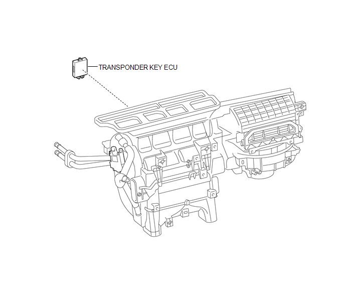
COMPONENTS
ILLUSTRATION
Installation
INSTALLATION
PROCEDURE
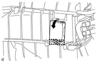
1. INSTALL TRANSPONDER KEY ECU
|
(a) Engage the 2 guides to move the transponder key ECU in the direction of the arrow to install the transponder key ECU. |
|
2. INSTALL AIR CONDITIONING UNIT ASSEMBLY
(See page .gif) )
)
Removal
REMOVAL
PROCEDURE
1. REMOVE AIR CONDITIONING UNIT ASSEMBLY
(See page .gif) )
)
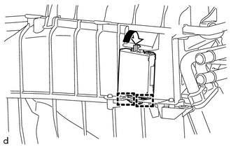
2. REMOVE TRANSPONDER KEY ECU
|
(a) Move the transponder key ECU in the direction of the arrow to disengage the 2 guides to remove the transponder key ECU. |
|
 Transponder Key Amplifier
Components
COMPONENTS
ILLUSTRATION
Installation
INSTALLATION
PROCEDURE
1. INSTALL TRANSPONDER KEY COIL
(a) Engage the 2 claws to install the transponder key coil.
...
 Exterior
...
Other materials:
Diagnostic Trouble Code Chart
DIAGNOSTIC TROUBLE CODE CHART
HINT:
If a trouble code is output during the DTC check, inspect the trouble areas listed
for that code. For details of the code, refer to the "See page" below.
Certification ECU (Smart Key ECU Assembly)
DTC Code
Detection Item
...
Installation
INSTALLATION
CAUTION / NOTICE / HINT
HINT:
Use the same procedure for both the RH and LH sides.
The procedure described below is for the LH side.
PROCEDURE
1. INSTALL REAR AIRBAG SENSOR
(a) Check that the ignition switch is off.
(b) Check that the battery negative (-) termin ...
Torque Converter Clutch Circuit Short to Battery or Open (P074015)
DESCRIPTION
Shift solenoid valve SL is turned on and off by signals from the ECM to control
the hydraulic pressure acting on the lock-up relay valve, which then controls operation
of the lock-up clutch.
DTC No.
DTC Detection Condition
Trouble Area
SA ...
