Toyota Tacoma (2015-2018) Service Manual: Tonneau Cover Assembly
Removal
REMOVAL
PROCEDURE
1. REMOVE TOP COVER SUB-ASSEMBLY
|
(a) Open the cover. |
|
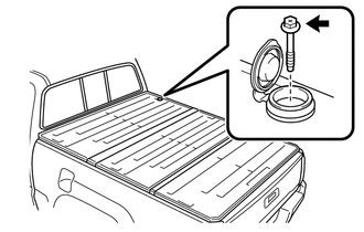
(b) Remove the bolt and top cover sub-assembly.
2. REMOVE REAR BODY SIDE PANEL PROTECTOR
Click here .gif)
Installation
INSTALLATION
PROCEDURE
1. INSTALL REAR BODY SIDE PANEL PROTECTOR
Click here .gif)
2. INSTALL TOP COVER SUB-ASSEMBLY
(a) Install the top cover sub-assembly with the bolt.
Torque:
27.3 N┬Ęm {278 kgf┬Ęcm, 20 ft┬Ęlbf}
(b) Close the cover.
 Reassembly
REASSEMBLY
PROCEDURE
1. INSTALL NO. 3 REAR BODY NAME PLATE (for 2GR-FKS)
2. INSTALL NO. 2 REAR BODY NAME PLATE (for 4WD)
3. INSTALL SIDE GATE SUPPORT FEMALE HINGE RH
(a) Engage ...

Other materials:
Inspection
INSPECTION
PROCEDURE
1. INSPECT AUTO HIGH BEAM SWITCH
*a
Component without harness connected
(Auto High Beam Switch)
(a) Check the resistance.
(1) Measure the resistance according to the value(s) in the table below.
Standard Resistance:
Tester C ...
Transfer Shift Motor Limit Switch Circuit (P17AC)
DESCRIPTION
When the transfer switches modes, the TL1, TL2 and TL3 terminals of the limit
switch are in one of the ON/OFF combinations listed in the table below.
Terminal
When 2WD
Switching between 2WD and H4
When H4
Switching between H4 and ...
Removal
REMOVAL
PROCEDURE
1. REMOVE INTAKE MANIFOLD
(See page )
2. REMOVE WIRE HARNESS CLAMP BRACKET
(a) Remove the 2 bolts and wire harness clamp bracket.
3. REMOVE FUEL TUBE SUB-ASSEMBLY
(a) Disconnect the fuel tube sub-assembly from ...
