Toyota Tacoma (2015-2018) Service Manual: Installation
INSTALLATION
PROCEDURE
1. INSTALL REAR DOOR GLASS SUB-ASSEMBLY
|
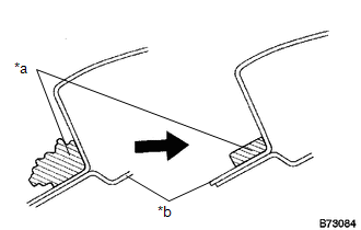
(a) Clean and shape the contact surface of the vehicle body. Text in Illustration
(1) Using a knife, cut away excess adhesive on the contact surface of the vehicle body as shown in the illustration. NOTICE: Leave as much adhesive on the vehicle body as possible. |
|
(b) Clean the contact surface of the vehicle body with a piece of cloth saturated with non-residue solvent.
(c) Apply Primer M to the exposed part of the vehicle body.
NOTICE:
- Do not apply too much Primer M.
- Do not coat the adhesive with primer M.
- Be careful when applying primer to the panel joints and spot welds.
(d) Using a brush or sponge, coat the application area of adhesive with primer G as shown in the illustration.
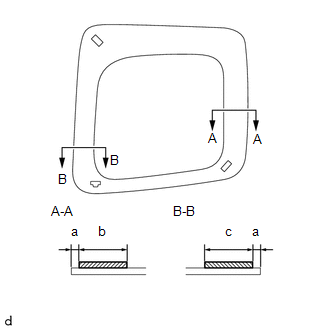 Text in Illustration
.png) |
Primer G |
Specification:
|
Area |
Measurement |
|---|---|
|
a |
5 mm (0.197 in.) |
|
b |
20 mm (0.787 in.) |
|
c |
26 mm (1.023 in.) |
NOTICE:
Do not apply too much Primer G.
|
(e) Cut off the tip of the sealer gun nozzle as shown in the illustration. Text in Illustration
|
|
(f) Load the sealer gun with the cartridge.
(g) Apply a bead of adhesive to the location shown in the illustration.
Specification:
|
Area |
Measurement |
|---|---|
|
a |
8 mm (0.315 in.) |
|
b |
12 mm (0.472 in.) |
|
c |
13 mm (0.512 in.) |
HINT:
After cutting off the tip, use all adhesive within the time indicated in the table below.
Usage time frame:
|
Temperature |
Usage Time Frame |
|---|---|
|
35°C (95°F) |
15 minutes |
|
20°C (68°F) |
1 hour 40 minutes |
|
5°C (41°F) |
8 hours |
(h) Install the quarter window assembly:
(1) Install the suction cups to the rear door glass assembly.
(2) Using suction cups, engage the 2 side window clips and rear door glass clip to install the rear door glass assembly.
NOTICE:
Install the rear door glass assembly after primer M on the vehicle body has been allowed to dry (approximately 3 minutes).
(3) Lightly press the front surface of the rear door glass assembly to ensure that the rear door glass assembly is securely fit to the vehicle body.
(4) Using a scraper, remove any excess or protruding adhesive.
(5) Hold the rear door glass assembly in place securely with protective tape or equivalent until the adhesive hardens.
NOTICE:
Do not drive the vehicle for the time described in the table below.
Minimum Time:
|
Temperature |
Minimum Time Prior to Driving Vehicle |
|---|---|
|
35°C (95°F) |
1 hour 30 minutes |
|
20°C (68°F) |
5 hours |
|
5°C (41°F) |
24 hours |
2. CHECK REAR DOOR GLASS SUB-ASSEMBLY
(a) After the adhesive has hardened, apply water from the outside of the vehicle. Check that no water leaks into the cabin.
(b) If water leaks into the cabin, allow the water to dry and add adhesive.
(c) Remove the protective tape.
3. INSTALL REAR DOOR TRIM BOARD SUB-ASSEMBLY
.gif)
4. INSTALL DOOR PULL HANDLE
5. INSTALL ACCESS PANEL INSIDE HANDLE BEZEL
6. INSTALL LAP BELT OUTER ANCHOR COVER
7. INSTALL REAR ACCESS PANEL WEATHERSTRIP
 Removal
REMOVAL
CAUTION / NOTICE / HINT
HINT:
Use the same procedure for both the RH and LH side.
The procedure described below is for the LH side.
PROCEDURE
1. REMOVE REAR ACCESS PANEL ...
 Windshield Glass
...
Other materials:
Definition Of Terms
DEFINITION OF TERMS
Term
Definition
Monitor Description
Description of what the ECM monitors and how it detects malfunctions
(monitoring purpose and details).
Related DTCs
A group of diagnostic trouble codes that are ...
Components
COMPONENTS
ILLUSTRATION
*1
COWL TOP VENTILATOR LOUVER SUB-ASSEMBLY
*2
FRONT FENDER UPPER PROTECTOR LH
*3
FRONT FENDER UPPER PROTECTOR RH
*4
FRONT WIPER ARM HEAD CAP
*5
WINDSH ...
Open or Short in Rear Speed Sensor RH Circuit (C1407,C1408)
DESCRIPTION
Refer to DTCs C1401 and C1402 (See page ).
DTC Code
DTC Detection Condition
Trouble Area
C1407
C1408
Either condition is met:
An open in the speed sensor signal circuit continues for 0.5
seconds or mor ...
