Toyota Tacoma (2015-2018) Service Manual: Reassembly
REASSEMBLY
PROCEDURE
1. INSTALL NO. 3 REAR BODY NAME PLATE (for 2GR-FKS)
.gif)
2. INSTALL NO. 2 REAR BODY NAME PLATE (for 4WD)
3. INSTALL SIDE GATE SUPPORT FEMALE HINGE RH
|
(a) Engage the claw to install the side gate support female hinge RH. |
|
.png)
4. INSTALL TAIL GATE HINGE ASSEMBLY RH
|
(a) Using a T40 "TORX" socket wrench, install the tail gate hinge assembly RH with the bolt and 2 screws. Torque: Bolt : 27 N·m {275 kgf·cm, 20 ft·lbf} Screw : 27 N·m {275 kgf·cm, 20 ft·lbf} |
|
.png)
5. INSTALL TAIL GATE HINGE ASSEMBLY LH
|
(a) Using a T40 "TORX" socket wrench, install the tail gate hinge assembly LH with the bolt and 2 screws. Torque: Bolt : 27 N·m {275 kgf·cm, 20 ft·lbf} Screw : 27 N·m {275 kgf·cm, 20 ft·lbf} |
|
.png)
6. INSTALL TAIL GATE STAY ASSEMBLY
|
(a) Using a T40 "TORX" socket wrench, install the tail gate stay assembly with the tail gate stay shaft and washer. Torque: 26 N·m {260 kgf·cm, 19 ft·lbf} HINT: Use the same procedure for the LH side and RH side. |
|
.png)
7. INSTALL TAIL GATE STAY STOPPER
|
(a) Using a T40 "TORX" socket wrench, install the tail gate stopper with the tail gate stay shaft. Torque: 26 N·m {260 kgf·cm, 19 ft·lbf} HINT: Use the same procedure for the LH side and RH side. |
|
.png)
8. INSTALL TAIL GATE
|
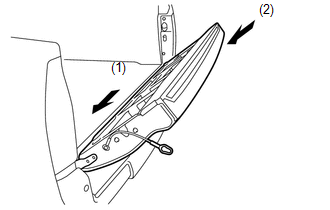
(a) Install the tail gate onto the vehicle by engaging the hinge on the left side first and then the hinge on the right side. NOTICE: Be careful not to drop the tail gate. |
|
|
(b) Engage the tail gate stay to the tail gate stay stopper as shown in the illustration. HINT: Use the same procedure for the LH side and RH side. |
|
|
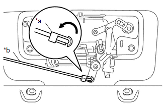
(c) Engage the 2 guides and 2 claws to connect the wire harness from the tail gate. |
|
.png)
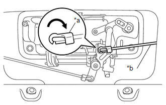
(d) Engage the clamp.
Text in Illustration|
*a |
Guide |
|
*b |
Clamp |
|
(e) Engage the clamp. |
|
.png)
9. INSTALL TAIL GATE LOCK STRIKER
|
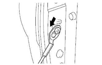
(a) Using a T40 "TORX" socket wrench, install the tail gate lock striker with the 2 bolts. Torque: 29 N·m {296 kgf·cm, 21 ft·lbf} HINT: Use the same procedure for the LH side and RH side. |
|
.png)
10. INSTALL TAIL GATE HANDLE ASSEMBLY
|
(a) Engage the guide to install the tail gate handle assembly. |
|
.png)
(b) Install the 2 bolts.
Torque:
5.5 N·m {56 kgf·cm, 49 in·lbf}
11. INSTALL TAIL GATE LOCK CONTROL LINK
|
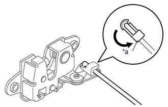
(a) Rotate the snap as shown in the illustration to engage the snap to install the tail gate lock control link to tail gate lock assembly LH. Text in Illustration
HINT: Use the same procedure for the LH side and RH side. |
|
12. INSTALL TAIL GATE LOCK ASSEMBLY LH
|
(a) Using a T40 "TORX" socket wrench, install the tail gate lock assembly LH with the 2 bolts. Torque: 29 N·m {296 kgf·cm, 21 ft·lbf} |
|
.png)
(b) Engage the clamp.
|
(c) Rotate the snap as shown in the illustration to engage the snap to install the tail gate lock control link to tail gate handle assembly. Text in Illustration
|
|
13. INSTALL TAIL GATE LOCK ASSEMBLY RH
|
(a) Using a T40 "TORX" socket wrench, install the tail gate lock assembly RH with the 2 bolts. Torque: 29 N·m {296 kgf·cm, 21 ft·lbf} |
|
.png)
(b) Engage the clamp.
|
(c) Rotate the snap as shown in the illustration to engage the snap to install the tail gate lock control link to tail gate handle assembly. Text in Illustration
|
|
14. INSTALL REAR TELEVISION CAMERA ASSEMBLY
15. INSTALL TAIL GATE SERVICE HOLE COVER
|
(a) Using a T30 "TORX" socket wrench, install the tail gate service hole cover with the 8 screws. |
|
.png)
16. INSTALL TAIL GATE PROTECTOR
(See page )
 Disassembly
DISASSEMBLY
PROCEDURE
1. REMOVE TAIL GATE PROTECTOR
(See page )
2. REMOVE TAIL GATE SERVICE HOLE COVER
(a) Using a T30 "TORX" socket wrench, remove the 8 screws and tail gat ...
 Tonneau Cover Assembly
Removal
REMOVAL
PROCEDURE
1. REMOVE TOP COVER SUB-ASSEMBLY
(a) Open the cover.
(b) Remove the bolt and top cover sub-assembly.
2. REMOVE RE ...
Other materials:
Installation
INSTALLATION
PROCEDURE
1. INSTALL WINDSHIELD WIPER MOTOR ASSEMBLY
(a) Apply MP grease to the crank arm pivot of the windshield wiper motor
assembly.
Text in Illustration
*1
Crank Arm Pivot
...
Road Test
ROAD TEST
PROBLEM SYMPTOM CONFIRMATION
HINT:
The dynamic radar cruise control system has 2 cruise control modes:
constant speed control mode and vehicle-to-vehicle distance control mode.
Vehicle-to-vehicle distance control mode is selected by default when
the dyna ...
Removal
REMOVAL
PROCEDURE
1. REMOVE REAR SEAT CUSHION ASSEMBLY
2. REMOVE NO. 4 ROOM PARTITION COVER LH
3. REMOVE NO. 4 ROOM PARTITION COVER RH
4. REMOVE NO. 3 ROOM PARTITION COVER
5. REMOVE BACK PANEL GARNISH HOLE PLUG
6. REMOVE BACK PANEL TRIM
7. REMOVE FRONT DOOR SCUFF PLATE ...
