Toyota Tacoma (2015-2018) Service Manual: System Diagram
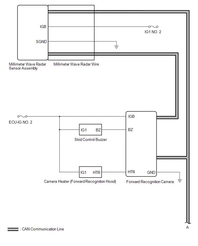
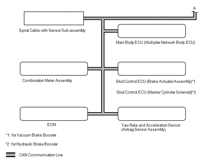
SYSTEM DIAGRAM
 Communication Table
|
Sender |
Receiver |
Signal |
Line |
|---|---|---|---|
| *1: for Vacuum Brake Booster
*2: for Hydraulic Brake Booster |
|||
|
Millimeter Wave Radar Sensor Assembly |
Forward Recognition Camera |
|
CAN |
|
ECM |
Forward Recognition Camera |
|
CAN |
|
Forward Recognition Camera |
|
CAN |
|
Yaw Rate and Acceleration Sensor (Airbag Sensor Assembly) |
Forward Recognition Camera |
Vehicle yaw rate sensor signal |
CAN |
|
Main Body ECU (Multiplex Network Body ECU) |
Forward Recognition Camera |
Destination information signal |
CAN |
 System Description
SYSTEM DESCRIPTION
GENERAL DESCRIPTION
(a) The forward recognition camera processes the image captured by the monocular
camera to detect lane markers, vehicles, pedestrians, traffic signs, etc. Th ...
 How To Proceed With Troubleshooting
CAUTION / NOTICE / HINT
HINT:
Use these procedures to troubleshoot the forward recognition camera
system.
*: Use the Techstream.
PROCEDURE
1.
VEHICLE B ...
Other materials:
Brake Fluid(for Hydraulic Brake Booster)
On-vehicle Inspection
ON-VEHICLE INSPECTION
PROCEDURE
1. INSPECT FLUID LEVEL IN RESERVOIR
(a) Turn the ignition switch to OFF, and depress the brake pedal more
than 40 times (until the pedal reaction feels light and pedal stroke becomes
longer), and adjust the fluid level to ...
All Doors LOCK/UNLOCK Functions do not Operate Via Door Control Switch or Door
Key Cylinder
DESCRIPTION
The main body ECU (multiplex network body ECU) receives switch signals from the
power window regulator master switch assembly and driver door key cylinder lock
or unlock switch signals from the front door lock assembly. The main body ECU (multiplex
network body ECU) activates the ...
Push Switch / Key Unlock Warning Switch Malfunction (B2780)
DESCRIPTION
This DTC is stored if the transponder key ECU assembly does not detect that the
unlock warning switch assembly is ON even when the key is in the ignition key cylinder.
Under normal conditions, the unlock warning switch assembly is ON when the key is
in the ignition key cylinder.
...
