Toyota Tacoma (2015-2018) Service Manual: Removal
REMOVAL
PROCEDURE
1. PRECAUTION
CAUTION:
Be sure to read Precaution thoroughly before servicing (See page
.gif) ).
).
NOTICE:
After turning the ignition switch off, waiting time may be required before disconnecting the cable from the negative (-) battery terminal. Therefore, make sure to read the disconnecting the cable from the negative (-) battery terminal notices before proceeding with work.
Click here
2. DISCONNECT CABLE FROM NEGATIVE BATTERY TERMINAL
CAUTION:
Wait at least 90 seconds after disconnecting the cable from the negative (-) battery terminal to disable the SRS system.
NOTICE:
When disconnecting the cable, some systems need to be initialized after the cable is reconnected.
Click here
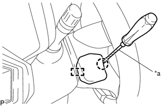
3. REMOVE LOWER NO. 3 STEERING WHEEL COVER
|
(a) Using a screwdriver with its tip wrapped in protective tape, disengage the claw and guide to remove the lower No. 3 steering wheel cover. Text in Illustration
|
|
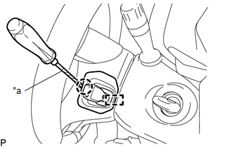
4. REMOVE LOWER NO. 2 STEERING WHEEL COVER
|
(a) Using a screwdriver with its tip wrapped in protective tape, disengage the claw and guide to remove the lower No. 2 steering wheel cover. Text in Illustration
|
|
5. REMOVE STEERING PAD
CAUTION:
When storing the steering pad, keep the airbag deployment side facing upward.
(a) Check that the ignition switch is off.
(b) Check that the cable is disconnected from the negative (-) battery terminal.
NOTICE:
Wait at least 90 seconds after disconnecting the cable from the negative (-) battery terminal to disable the SRS system.
|
(c) Using a T30 "TORX" socket wrench, loosen the 2 screws until the groove along the screw circumference catches on the screw case. |
|
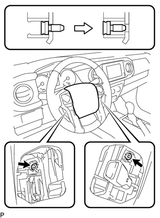
(d) Pull the steering pad toward you.
|
(e) Using a screwdriver with its tip wrapped in protective tape, release the 2 airbag connector locks. Text in Illustration
|
|
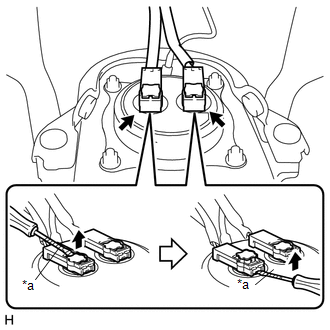
(f) Disconnect the 2 airbag connectors.
NOTICE:
When disconnecting any airbag connector, take care not to damage the airbag wire harness.
(g) Disconnect the horn terminal to remove the steering pad.
 On-vehicle Inspection
ON-VEHICLE INSPECTION
PROCEDURE
1. INSPECT STEERING PAD (for Vehicle not Involved in Collision)
(a) Perform a diagnostic system check (See page
).
(b) With the steering pad installed on the vehi ...
 Installation
INSTALLATION
PROCEDURE
1. INSTALL STEERING PAD
(a) Check that the ignition switch is off.
(b) Check that the cable is disconnected from the negative (-) battery terminal.
CAUTION:
Wait at least ...
Other materials:
System Diagram
SYSTEM DIAGRAM
Communication Table
Sender
Receiver
Signal
Line
*1: for Vacuum Brake Booster
*2: for Hydraulic Brake Booster
Millimeter Wave Radar Sensor Assembly
Forward Recognition Camera
...
Installation
INSTALLATION
CAUTION / NOTICE / HINT
HINT:
The following procedures are for BD22 (w/o Differential Lock).
PROCEDURE
1. INSTALL DIFFERENTIAL CARRIER ASSEMBLY REAR
(a) Clean the contact surfaces of the rear differential carrier assembly and
axle housing.
(b) Install the rear differential carr ...
Horn System
Parts Location
PARTS LOCATION
ILLUSTRATION
Precaution
PRECAUTION
1. IGNITION SWITCH EXPRESSIONS
(a) The type of ignition switch used on this model differs depending on the specifications
of the vehicle. The expressions listed in the table below are used in this section.
Exp ...
