Toyota Tacoma (2015-2018) Service Manual: Heater Circuit (C1AAE)
DESCRIPTION
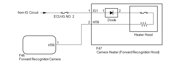
The forward recognition camera controls the current supplied to the camera heater (forward recognition hood).
If the forward recognition camera detects a malfunction in the camera heater (forward recognition hood) circuit, DTC C1AAE is stored.
|
DTC No. |
Detection Item |
DTC Detection Condition |
Trouble Area |
|---|---|---|---|
|
C1AAE |
Heater Circuit |
Either of the following conditions is met after 3 seconds have elapsed since the ignition switch was turned to ON:
|
|
|
Vehicle Condition |
Vehicle Condition |
||
|---|---|---|---|
|
Pattern 1 |
Pattern 2 |
||
|
Diagnosis Condition |
Ignition switch ON |
â—‹ |
â—‹ |
|
Malfunction Status |
|
â—‹ |
|
|
â—‹ |
||
|
Detection Time |
5 seconds or more |
5 seconds or more |
|
|
Number of Trips |
1 trip |
1 trip |
|
HINT:
If any of the detection patterns above are met, a DTC is output.
WIRING DIAGRAM
CAUTION / NOTICE / HINT
NOTICE:
- Inspect the fuses for circuits related to this system before performing the following procedure.
- When replacing the forward recognition camera, always replace it with a new one. If a forward recognition camera which was installed to another vehicle is used, the information stored in it will not match the information from the vehicle and a DTC may be stored.
- After replacing or removing/installing the forward recognition camera
or windshield glass, make sure to perform forward recognition camera axis
adjustment.
Click here
.gif)
PROCEDURE
|
1. |
CHECK FOR DTCs (FORWARD RECOGNITION CAMERA SYSTEM) |
(a) Clear the DTCs.
Click here
(b) Make sure that the DTC detection conditions are met.
HINT:
If the conditions are not met, the system cannot detect the malfunction.
(c) Check for DTCs.
Click here
|
Result |
Proceed to |
|---|---|
|
DTC C1AAE is not output |
A |
|
DTC C1AAE is output |
B |
| A | .gif) |
USE SIMULATION METHOD TO CHECK |
|
.gif)
|
2. |
CHECK CAMERA HEATER (FORWARD RECOGNITION HOOD) |
(a) Turn the ignition switch off.
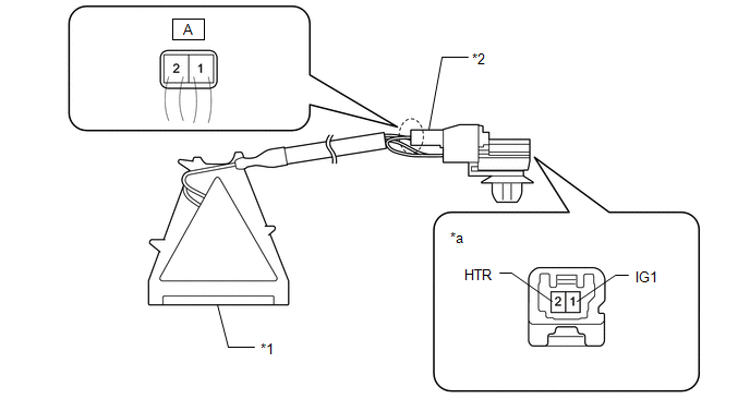
(b) Disconnect the F47 camera heater (forward recognition hood) connector.
|
*1 |
Camera Heater (Forward Recognition Hood) |
*2 |
Diode |
|
*a |
Component without harness connected |
- |
- |
(c) Measure the resistance according to the value(s) in the table below.
Standard Resistance:
|
Tester Connection |
Condition |
Specified Condition |
|
|---|---|---|---|
|
2 (HTR) - A-2 |
Always |
Ignition switch off |
36.1 to 39.9 Ω |
|
1 (IG1) - A-1 |
Always |
Ignition switch off |
Below 1 Ω |
|
A-1 - A-2 |
HINT: If the tester probes are connected to the wrong terminals, due to the existence of the diode, current will not flow and the result will be the same as for an open circuit. |
Ignition switch off |
Below 1 Ω |
(d) Connect the F47 camera heater (forward recognition hood) connector.
| NG | |
REPLACE CAMERA HEATER (FORWARD RECOGNITION HOOD) |
|
|
3. |
CHECK HARNESS AND CONNECTOR (CAMERA HEATER (FORWARD RECOGNITION HOOD)) |
|
(a) Disconnect the camera heater (forward recognition hood) connector. |
|
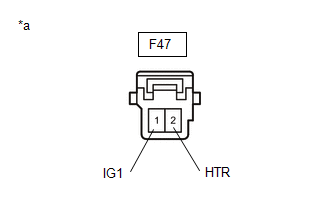
(b) Measure the voltage according to the value(s) in the table below.
Standard Voltage:
|
Tester Connection |
Switch Condition |
Specified Condition |
|---|---|---|
|
F47-1 (IG1) - Body ground |
Ignition switch ON |
11 to 14 V |
|
F47-1 (IG1) - Body ground |
Ignition switch off |
Below 1.5 V |
(c) Connect the camera heater (forward recognition hood) connector.
| NG | |
REPAIR OR REPLACE HARNESS OR CONNECTOR (POWER SOURCE CIRCUIT) |
|
|
4. |
CHECK HARNESS AND CONNECTOR (CAMERA HEATER (FORWARD RECOGNITION HOOD) - FORWARD RECOGNITION CAMERA) |
(a) Disconnect the F47 camera heater (forward recognition hood) connector.
(b) Disconnect the F46 forward recognition camera connector.
(c) Measure the resistance according to the value(s) in the table below.
Standard Resistance:
|
Tester Connection |
Switch Condition |
Specified Condition |
|---|---|---|
|
F47-2 (HTR) - F46-1 (HTR) |
Always |
Below 1 Ω |
|
F47-2 (HTR) or F46-1 (HTR) - Body ground |
Always |
10 kΩ or higher |
(d) Connect the F46 forward recognition camera connector.
(e) Connect the F47 camera heater (forward recognition hood) connector.
| OK | |
REPLACE FORWARD RECOGNITION CAMERA |
| NG | |
REPAIR OR REPLACE HARNESS OR CONNECTOR (CAMERA HEATER (FORWARD RECOGNITION HOOD) - FORWARD RECOGNITION CAMERA) |
 Yaw Rate Sensor Circuit (C1AA4,C1AA5)
DESCRIPTION
The forward recognition camera receives vehicle stability signals from the yaw
rate and acceleration sensor (airbag sensor assembly). If the yaw rate and acceleration
sensor (airbag s ...
 Front Camera Module Incorrect Axial Gap (C1AA8,C1AA9)
DESCRIPTION
If the forward recognition camera detects that the forward recognition camera
axis has deviated, DTC C1AA8 is stored. Also, if Forward Recognition Camera Axis
Adjustment is not perfor ...
Other materials:
Wireless remote control*
The wireless remote control can be used to lock and unlock the vehicle from outside
the vehicle.
Locks all doors
Unlocks all doors
Pressing the button unlocks the driver’s door. Pressing the button again within
3 seconds unlocks the other doors.
Sounds alarm (push and hold)
■Op ...
Washer Level Warning Switch
Components
COMPONENTS
ILLUSTRATION
Inspection
INSPECTION
PROCEDURE
1. INSPECT LEVEL WARNING SWITCH ASSEMBLY
HINT:
This check should be performed with the windshield washer motor and pump assembly
installed on the washer jar.
(a) Fill the washer jar with washer fluid.
(b) ...
How To Proceed With Troubleshooting
CAUTION / NOTICE / HINT
HINT:
Perform the following procedure to troubleshoot the dynamic radar cruise
control system.
*: Use the Techstream.
PROCEDURE
1.
VEHICLE BROUGHT TO WORKSHOP
NEXT
...
