Toyota Tacoma (2015-2018) Service Manual: 4WD Control Switch Circuit
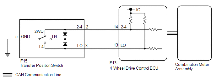
WIRING DIAGRAM
PROCEDURE
|
1. |
CONFIRM PROBLEM SYMPTOM |
(a) Confirm the problem symptoms.
Result|
Result |
Proceed to |
|---|---|
|
The 4WD indicator light (green) and 4LO indicator light remain off |
A |
|
The 4WD indicator light (green) remains illuminated, and the 4LO indicator light remains off |
B |
|
The 4WD indicator light (green) and 4LO indicator light remain illuminated |
C |
| B | .gif) |
GO TO STEP 6 |
| C | |
GO TO STEP 7 |
|
.gif)
|
2. |
CHECK 4WD INDICATOR LIGHT (GREEN) |
(a) Turn the ignition switch to ON.
(b) for Automatic Transmission:
Move the shift lever to N.
for Manual Transmission:
Depress the clutch pedal.
(c) Turn the transfer position switch to H4.
(d) Wait for 60 seconds.
(e) Check the 4WD indicator light (green).
Result|
Result |
Proceed to |
|---|---|
|
The 4WD indicator light (green) blinks*1 or illuminates |
A |
|
The 4WD indicator light (green) rapidly blinks*2 or remains off |
B |
- *1 (Blinking): Blinks at 0.5 second intervals (0.5 seconds on and 0.5 seconds off)
- *2 (Rapidly blinking): Blinks at 0.25 second intervals (0.25 seconds on and 0.25 seconds off)
| A | |
END |
|
|
3. |
CHECK FOR DTC |
(a) Turn the transfer position switch to L4.
(b) Check if DTC P279E is output after 60 seconds elapse (See page
.gif) ).
).
|
Result |
Proceed to |
|---|---|
|
DTC P279E is not output |
A |
|
DTC P279E is output |
B |
| B | |
REPAIR CIRCUIT INDICATED BY OUTPUT CODE |
|
|
4. |
CHECK CAN COMMUNICATION LINE |
(a) Select "Bus Check" from the System Selection Menu screen, and follow the
prompts on the screen to inspect the CAN Bus (See page
).
OK:
"Bus Check" indicates no malfunctions in CAN communication.
| NG | |
CHECK CAN COMMUNICATION SYSTEM |
|
|
5. |
CHECK TRANSFER POSITION SWITCH |
|
(a) Remove the transfer position switch with its connector still connected. |
|
(b) Measure the voltage according to the value(s) in the table below.
Standard Voltage:
|
Tester Connection |
Switch Condition |
Specified Condition |
|---|---|---|
|
F15-2 (2-4) - Body ground |
Ignition switch ON 2WD position |
Below 1.5 V |
|
Ignition switch ON H4 position |
Below 1.5 V |
|
|
Ignition switch ON L4 position |
10 to 14 V |
|
|
F15-3 (LO) - Body ground |
Ignition switch ON 2WD position |
10 to 14 V |
|
Ignition switch ON H4 position |
Below 1.5 V |
|
|
Ignition switch ON L4 position |
Below 1.5 V |
|
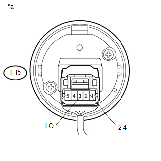
*a |
Component with harness connected (Transfer Position Switch) |
| OK | |
CHECK METER / GAUGE SYSTEM |
| NG | |
REPLACE TRANSFER POSITION SWITCH |
|
6. |
CHECK 4WD INDICATOR LIGHT (GREEN) |
(a) Turn the ignition switch to ON.
(b) for Automatic Transmission:
Move the shift lever to N.
for Manual Transmission:
Depress the clutch pedal.
(c) Turn the transfer position switch to 2WD.
(d) Wait for 60 seconds.
(e) Check the 4WD indicator light (green).
Result|
Result |
Proceed to |
|---|---|
|
The 4WD indicator light (green) blinks*1 or turns off |
A |
|
The 4WD indicator light (green) rapidly blinks*2 or remains on |
B |
- *1 (Blinking): Blinks at 0.5 second intervals (0.5 seconds on and 0.5 seconds off)
- *2 (Rapidly blinking): Blinks at 0.25 second intervals (0.25 seconds on and 0.25 seconds off)
| A | |
END |
| B | |
GO TO DTC P279E |
|
7. |
CHECK 4LO INDICATOR LIGHT |
HINT:
Perform the following procedures with the vehicle stopped.
(a) Turn the ignition switch to ON.
(b) for Automatic Transmission:
Move the shift lever to N.
for Manual Transmission:
Depress the clutch pedal.
(c) Turn the transfer position switch to H4.
(d) Wait for 60 seconds.
(e) Check the 4LO indicator light.
Result|
Result |
Proceed to |
|---|---|
|
The 4LO indicator light blinks*1 or turns off |
A |
|
The 4LO indicator light rapidly blinks*2 or remains on |
B |
- *1 (Blinking): Blinks at 0.5 second intervals (0.5 seconds on and 0.5 seconds off)
- *2 (Rapidly blinking): Blinks at 0.25 second intervals (0.25 seconds on and 0.25 seconds off)
| A | |
END |
|
|
8. |
CHECK FOR DTC |
(a) Turn the transfer position switch to 2WD.
(b) Check if DTC P279E is output after 60 seconds elapse (See page
).
|
Result |
Proceed to |
|---|---|
|
DTC P279E is not output |
A |
|
DTC P279E is output |
B |
| B | |
REPAIR CIRCUIT INDICATED BY OUTPUT CODE |
|
|
9. |
CHECK TRANSFER POSITION SWITCH |
|
(a) Remove the transfer position switch with its connector still connected. |
|
(b) Measure the voltage according to the value(s) in the table below.
Standard Voltage:
|
Tester Connection |
Switch Condition |
Specified Condition |
|---|---|---|
|
F15-2 (2-4) - Body ground |
Ignition switch ON 2WD position |
Below 1.5 V |
|
Ignition switch ON H4 position |
Below 1.5 V |
|
|
Ignition switch ON L4 position |
10 to 14 V |
|
|
F15-3 (LO) - Body ground |
Ignition switch ON 2WD position |
10 to 14 V |
|
Ignition switch ON H4 position |
Below 1.5 V |
|
|
Ignition switch ON L4 position |
Below 1.5 V |
|
*a |
Component with harness connected (Transfer Position Switch) |
| OK | |
CHECK CAN COMMUNICATION SYSTEM |
| NG | |
REPLACE TRANSFER POSITION SWITCH |
 Lost Communication with ECM / PCM "A" (U0100,U0122)
DESCRIPTION
This DTC is output when communication is lost with the skid control ECU (brake
actuator assembly) or ECM.
DTC No.
Detection Item
DTC Detection Conditio ...
 ECU Power Source Circuit
WIRING DIAGRAM
CAUTION / NOTICE / HINT
NOTICE:
Inspect the fuses for circuits related to this system before performing the following
inspection procedure.
PROCEDURE
1.
...
Other materials:
Terminals Of Ecu
TERMINALS OF ECU
1. CHECK SLIDING ROOF ECU (SLIDING ROOF DRIVE GEAR SUB-ASSEMBLY)
(a) Disconnect the S50 sliding roof ECU (sliding roof drive gear sub-assembly)
connector.
(b) Measure the resistance and voltage according to the value(s) in the table
below.
HINT:
Measure the values on the ...
XM Tuner Antenna Disconnected (B15FE,B15FF)
DESCRIPTION
These DTCs are stored when a malfunction occurs in the antenna assembly with
holder which is connected to the navigation receiver assembly assembly.
DTC No.
DTC Detection Condition
Trouble Area
B15FE
The antenna assembly wi ...
Cup holders
Type A (Bench type front seat)
Type B (Separated type front seats
with an automatic transmission)
Type C (Separated type front seats
with a manual transmission)
■Removing the cup holder
Type A (Bench type front seat)
Pull the cup holder up.
Type B (Separated type front s ...
