Toyota Tacoma (2015-2018) Service Manual: Sound Signal Circuit between Radio Receiver and Stereo Component Amplifier
DESCRIPTION
The navigation receiver assembly sends a sound signal to the stereo component amplifier assembly via this circuit.
The sound signal that has been sent is amplified by the stereo component amplifier assembly, and then is sent to the speakers.
If there is an open or short in the circuit, sound cannot be heard from the speakers even if there is no malfunction in the stereo component amplifier assembly or speakers.
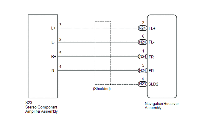
WIRING DIAGRAM
PROCEDURE
|
1. |
CHECK HARNESS AND CONNECTOR (NAVIGATION RECEIVER ASSEMBLY - STEREO COMPONENT AMPLIFIER ASSEMBLY) |
(a) Disconnect the N23 and N24 navigation receiver assembly connector.
(b) Disconnect the S23 stereo component amplifier assembly connector.
(c) Measure the resistance according to the value(s) in the table below.
Standard Resistance:
|
Tester Connection |
Condition |
Specified Condition |
|---|---|---|
|
S23-3 (L+) - N24-2 (FL+) |
Always |
Below 1 Ω |
|
S23-2 (L-) - N24-6 (FL-) |
Always |
Below 1 Ω |
|
S23-5 (R+) - N24-1 (FR+) |
Always |
Below 1 Ω |
|
S23-4 (R-) - N24-5 (FR-) |
Always |
Below 1 Ω |
|
S23-3 (L+) - Body ground |
Always |
10 kΩ or higher |
|
S23-2 (L-) - Body ground |
Always |
10 kΩ or higher |
|
S23-5 (R+) - Body ground |
Always |
10 kΩ or higher |
|
S23-4 (R-) - Body ground |
Always |
10 kΩ or higher |
|
N23-4 (SLD2) - Body ground |
Always |
10 kΩ or higher |
| OK | .gif) |
PROCEED TO NEXT SUSPECTED AREA SHOWN IN PROBLEM SYMPTOMS TABLE |
| NG | |
REPAIR OR REPLACE HARNESS OR CONNECTOR |
 Speaker Circuit
DESCRIPTION
If there is a short in a speaker circuit, the stereo component amplifier assembly*1
or navigation receiver assembly*2 detects it and stops output to the speakers.
Thus sound cannot be ...
 Data Signal Circuit between Stereo Jack Adapter and Extension Module
DESCRIPTION
The No. 1 stereo jack adapter assembly sends the sound data signal or image data
signal from a USB device to the navigation receiver assembly via this circuit.
WIRING DIAGRAM
PROCED ...
Other materials:
High Pitched Horn
Components
COMPONENTS
ILLUSTRATION
Removal
REMOVAL
PROCEDURE
1. REMOVE RADIATOR GRILLE
Click here
2. REMOVE HIGH PITCHED HORN ASSEMBLY
(a) Disconnect the connector.
(b) Remove the bolt and high pitched horn assembly.
Inspection
...
Removal
REMOVAL
PROCEDURE
1. REMOVE REAR SEAT CUSHION ASSEMBLY
(a) Remove the 2 bolts and rear seat cushion assembly.
2. REMOVE REAR SEATBACK HINGE COVER
(a) for LH Side:
(1) Disengage the 6 claws to remove the 2 rear seatback hinge cov ...
Fail-safe Chart
FAIL-SAFE CHART
1. Fail-safe
This function minimizes the loss of operation when any abnormality occurs in
a sensor or solenoid.
Fail-safe Control List
Malfunction Part
Function
Transmission revolution sensor (NT)
During a transmission revolutio ...
