Toyota Tacoma (2015-2018) Service Manual: Air Fuel Ratio Sensor
Components
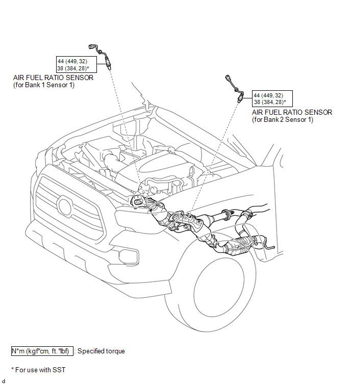
COMPONENTS
ILLUSTRATION
Removal
REMOVAL
PROCEDURE
1. REMOVE AIR FUEL RATIO SENSOR (for Bank 1 Sensor 1)
|
(a) Disconnect the air fuel ratio sensor connector. |
|
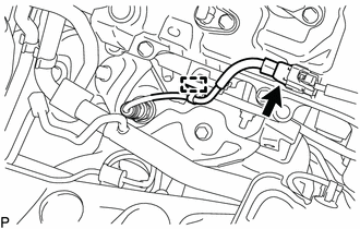
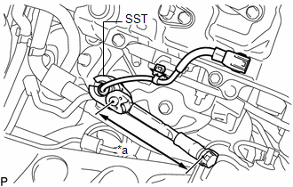
(b) Disengage the clamp to separate the air fuel ratio sensor wire.
|
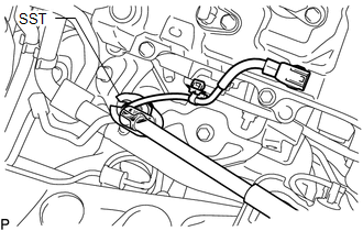
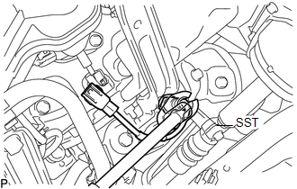
(c) Using SST, remove the air fuel ratio sensor from the exhaust manifold sub-assembly RH. SST: 09224-00011 |
|
2. REMOVE AIR FUEL RATIO SENSOR (for Bank 2 Sensor 1)
|
(a) Disconnect the air fuel ratio sensor connector. |
|
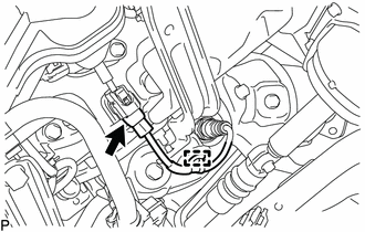
(b) Disengage the clamp to separate the air fuel ratio sensor wire.
|
(c) Using SST, remove the air fuel ratio sensor from the exhaust manifold sub-assembly LH. SST: 09224-00011 |
|
Inspection
INSPECTION
PROCEDURE
1. INSPECT AIR FUEL RATIO SENSOR
|
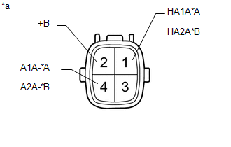
(a) Measure the resistance according to the value(s) in the table below. Text in Illustration
Standard Resistance (for Bank 1 Sensor 1):
Standard Resistance (for Bank 2 Sensor 1):
If the result is not as specified, replace the air fuel ratio sensor. |
|
Installation
INSTALLATION
PROCEDURE
1. INSTALL AIR FUEL RATIO SENSOR (for Bank 1 Sensor 1)
HINT:
Perform "Inspection After Repair" after replacing the air fuel ratio sensor (See
page .gif) ).
).
|
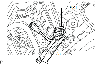
(a) Using SST, install the air fuel ratio sensor to the exhaust manifold sub-assembly RH. Text in Illustration
SST: 09224-00011 Torque: Specified tightening torque : 44 N·m {449 kgf·cm, 32 ft·lbf} HINT:
|
|
(b) Engage the clamp to install the air fuel ratio sensor wire.
(c) Connect the air fuel ratio sensor connector.
2. INSTALL AIR FUEL RATIO SENSOR (for Bank 2 Sensor 1)
HINT:
Perform "Inspection After Repair" after replacing the air fuel ratio sensor (See
page ).
|
(a) Using SST, install the air fuel ratio sensor to the exhaust manifold sub-assembly LH. Text in Illustration
SST: 09224-00011 Torque: Specified tightening torque : 44 N·m {449 kgf·cm, 32 ft·lbf} HINT:
|
|
(b) Engage the clamp to install the air fuel ratio sensor wire.
(c) Connect the air fuel ratio sensor connector.
 Accelerator Pedal
Components
COMPONENTS
ILLUSTRATION
On-vehicle Inspection
ON-VEHICLE INSPECTION
PROCEDURE
1. INSPECT ACCELERATOR PEDAL SENSOR ASSEMBLY
(a) Connect the Techstream to the DLC3.
(b) Turn the ...

Other materials:
Slip Indicator Light Remains ON
DESCRIPTION
The slip indicator light blinks during VSC or TRAC and AUTO LSD operation. When
the system fails, the slip indicator light comes on to warn the driver.
WIRING DIAGRAM
CAUTION / NOTICE / HINT
NOTICE:
When replacing the skid control ECU (master cylinder solenoid), perform ...
Installation
INSTALLATION
CAUTION / NOTICE / HINT
HINT:
Use the same procedure for both the RH and LH sides.
The procedure described below is for the LH side.
PROCEDURE
1. INSTALL SIDE AIRBAG SENSOR ASSEMBLY
(a) Check that the ignition switch is OFF.
(b) Check that the cable is disconnec ...
A/C ECU Vehicle Information Reading/Writing Processor Malfunction (B15F5)
DESCRIPTION
This DTC is stored when items controlled by the air conditioning amplifier assembly
cannot be customized via the audio and visual system vehicle customization screen.
HINT:
The air conditioning amplifier assembly controls the air conditioning system
related items that are customiz ...
