Toyota Tacoma (2015-2018) Service Manual: Removal
REMOVAL
PROCEDURE
1. REMOVE WATER INLET WITH THERMOSTAT SUB-ASSEMBLY
(See page .gif) )
)
2. REMOVE NO. 1 RADIATOR HOSE
3. REMOVE NO. 2 RADIATOR HOSE
4. DISCONNECT RADIATOR RESERVE TANK HOSE
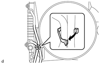
5. SEPARATE TRANSMISSION OIL COOLER HOSE (for Automatic Transmission)
|
(a) Disengage the clamp to separate the 2 transmission oil cooler hoses from the fan shroud. |
|
6. REMOVE FAN SHROUD
7. REMOVE COOLER COMPRESSOR ASSEMBLY
(See page )
8. REMOVE V-RIBBED BELT TENSIONER ASSEMBLY
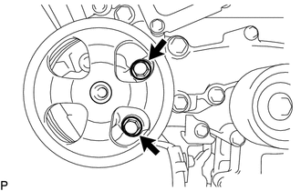
9. SEPARATE VANE PUMP ASSEMBLY
|
(a) Remove the 2 bolts and separate the vane pump assembly from the timing chain cover assembly. |
|
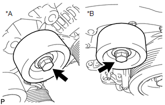
10. REMOVE NO. 2 IDLER PULLEY SUB-ASSEMBLY
|
(a) Remove the 2 bolts and 2 No. 2 idler pulley sub-assemblies from the timing chain cover assembly. Text in Illustration
|
|
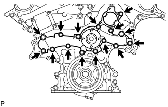
11. REMOVE ENGINE WATER PUMP ASSEMBLY
|
(a) Remove the 15 bolts, engine water pump assembly and gasket from the timing chain cover assembly. |
|
 On-vehicle Inspection
ON-VEHICLE INSPECTION
PROCEDURE
1. INSPECT FOR COOLANT LEAK
HINT:
The sliding surface inside the engine water pump assembly is lubricated
by engine coolant. As some engine coolant is d ...
 Installation
INSTALLATION
PROCEDURE
1. INSTALL ENGINE WATER PUMP ASSEMBLY
(a) Install the engine water pump assembly and a new gasket to the timing
chain cover assembly with the 15 bolts.
Torq ...
Other materials:
Front Radar Sensor Region Code Mismatch (C1A0A)
DESCRIPTION
When the destination information in the millimeter wave radar sensor assembly
and forward recognition camera do not match, DTC C1A0A is stored.
DTC No.
Detection Item
DTC Detection Condition
Trouble Area
MIL
C1A0 ...
Certification Ecu
Components
COMPONENTS
ILLUSTRATION
Installation
INSTALLATION
PROCEDURE
1. INSTALL CERTIFICATION ECU (SMART KEY ECU ASSEMBLY)
(a) Install the certification ECU (smart key ECU assembly) with the 2 nuts.
Torque:
6.5 N·m {66 kgf·cm, 58 in·lbf}
(b) Engage the clamp to install the wire ...
Freeze Frame Data
FREEZE FRAME DATA
DESCRIPTION
(a) When a pre-collision system DTC is stored, the millimeter wave radar sensor
assembly stores the current vehicle (ECU or sensor) state as Freeze Frame Data.
CHECK FREEZE FRAME DATA
(a) Connect the Techstream to the DLC3.
(b) Turn the ignition switch to ON.
(c ...
