Toyota Tacoma (2015-2018) Service Manual: On-vehicle Inspection
ON-VEHICLE INSPECTION
PROCEDURE
1. INSPECT FOR COOLANT LEAK
HINT:
- The sliding surface inside the engine water pump assembly is lubricated by engine coolant. As some engine coolant is discharged during normal operation, engine coolant residue (solids) may be found on the drain plug or the bottom of the engine water pump assembly. Also, engine coolant may leak if foreign matter enters the engine water pump assembly, however the sealing performance will recover when the foreign matter is pushed out or breaks into fine pieces. In this case, check the area around the engine water pump assembly.
- Before performing this inspection, check that there are no engine coolant leaks from any parts other than the engine water pump assembly. If there are leaks, inspect those areas first.
- Perform this inspection when the engine is cold.
(a) Visually check the engine water pump assembly.
(1) Check that engine coolant is not dripping from the engine water pump assembly.
HINT:
- If engine coolant is dripping, replace the engine water pump assembly.
- If engine coolant is not dripping, perform the following check.
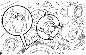
(b) Inspect the area around the engine water pump assembly.
HINT:
Check for deposits around the drain plug of the engine water pump assembly.
(1) Remove the fan pulley (See page .gif) ).
).
|
(2) Press a piece of thin paper towel against the drain plug or deposits on the lip of the drain plug and check that the paper towel is not wet. Text in Illustration
HINT:
|
|
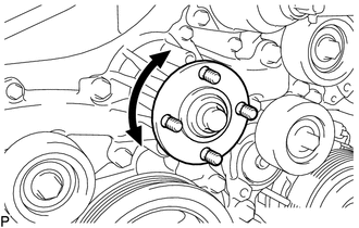
2. INSPECT ENGINE WATER PUMP ASSEMBLY
|
(a) Turn the pulley and check that the water pump bearing moves smoothly and quietly. If necessary, replace the engine water pump assembly. |
|
(b) Install the fan pulley (See page ).
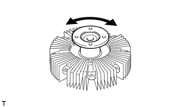
3. INSPECT FLUID COUPLING ASSEMBLY
(a) Remove the fan with fluid coupling assembly (See page
).
|
(b) Remove the 4 nuts and fan from the fluid coupling assembly. |
|

|
(c) Check that the fluid coupling assembly is not damaged and that no silicon oil leaks. If necessary, replace the fluid coupling assembly. |
|
(d) Install the fan to the fluid coupling assembly with the 4 nuts.
Torque:
10 N·m {102 kgf·cm, 7 ft·lbf}
(e) Install the fan with fluid coupling assembly (See page
).
 Components
COMPONENTS
ILLUSTRATION
ILLUSTRATION
...
 Removal
REMOVAL
PROCEDURE
1. REMOVE WATER INLET WITH THERMOSTAT SUB-ASSEMBLY
(See page )
2. REMOVE NO. 1 RADIATOR HOSE
3. REMOVE NO. 2 RADIATOR HOSE
4. DISCONNECT RADIATOR RESERVE TANK HOSE
5 ...
Other materials:
Problem Symptoms Table
PROBLEM SYMPTOMS TABLE
HINT:
Use the table below to help determine the cause of problem symptoms.
If multiple suspected areas are listed, the potential causes of the symptoms
are listed in order of probability in the "Suspected Area" column of the
table. Check each sy ...
Inspection
INSPECTION
PROCEDURE
1. INSPECT OIL PUMP RELIEF VALVE
(a) Coat the oil pump relief valve with engine oil and check that it
falls smoothly into the valve hole by its own weight.
If the valve does not fall smoothly, replace the timing chain cover assembly.
...
Freeze Frame Data
FREEZE FRAME DATA
DESCRIPTION
(a) When a pre-collision system DTC is stored, the millimeter wave radar sensor
assembly stores the current vehicle (ECU or sensor) state as Freeze Frame Data.
CHECK FREEZE FRAME DATA
(a) Connect the Techstream to the DLC3.
(b) Turn the ignition switch to ON.
(c ...
