Toyota Tacoma (2015-2018) Service Manual: Voice Recognition Microphone Disconnected (B1579)
DESCRIPTION
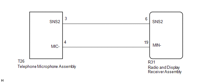
The radio and display receiver assembly and telephone microphone assembly are connected to each other using the microphone connection detection signal lines.
This DTC is stored when a microphone connection detection signal line is disconnected.
|
DTC Code |
DTC Detection Condition |
Trouble Area |
|---|---|---|
|
B1579 |
Telephone microphone signal is lost. |
|
WIRING DIAGRAM
PROCEDURE
|
1. |
INSPECT RADIO AND DISPLAY RECEIVER ASSEMBLY |
(a) Remove the radio and display receiver assembly with connectors still connected.
|
(b) Measure the resistance according to the value(s) in the table below. Standard Resistance:
|
|
| NG | .gif) |
REPLACE RADIO AND DISPLAY RECEIVER ASSEMBLY |
|
.gif)
|
2. |
CHECK HARNESS AND CONNECTOR (RADIO AND DISPLAY RECEIVER ASSEMBLY - TELEPHONE MICROPHONE ASSEMBLY) |
(a) Disconnect the R31 radio and display receiver assembly connector.
(b) Disconnect the T26 telephone microphone assembly connector.
(c) Measure the resistance according to the value(s) in the table below.
Standard Resistance:
|
Tester Connection |
Condition |
Specified Condition |
|---|---|---|
|
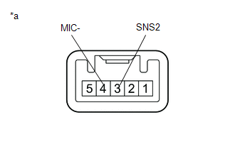
R31-6 (SNS2) - T26-3 (SNS2) |
Always |
Below 1 Ω |
|
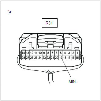
R31-19 (MIN-) - T26-4 (MIC-) |
Always |
Below 1 Ω |
|
R31-6 (SNS2) - Body ground |
Always |
10 kΩ or higher |
|
R31-19 (MIN-) - Body ground |
Always |
10 kΩ or higher |
| NG | |
REPAIR OR REPLACE HARNESS OR CONNECTOR |
|
|
3. |
INSPECT TELEPHONE MICROPHONE ASSEMBLY |
(a) Remove the telephone microphone assembly.
|
(b) Measure the resistance according to the value(s) in the table below. Standard Resistance:
|
|
| OK | |
REPLACE RADIO AND DISPLAY RECEIVER ASSEMBLY |
| NG | |
REPLACE TELEPHONE MICROPHONE ASSEMBLY |
 Sending Malfunction (Navigation to APGS) (U0073,U0100,U0140,U0155)
DESCRIPTION
These DTCs are stored when a malfunction occurs in the CAN communication circuit.
DTC No.
DTC Detection Condition
Trouble Area
U0073
...
 Satellite Radio Broadcast cannot be Received
CAUTION / NOTICE / HINT
NOTICE:
Some satellite radio broadcasts require payment. A contract must be
made between a satellite radio company and the user. If the contract expires,
it w ...
Other materials:
Terminals Of Ecu
TERMINALS OF ECU
1. REAR TELEVISION CAMERA ASSEMBLY
(a) Disconnect the T22 television camera assembly connector.
(b) Measure the voltage and resistance according to the value(s) in the table
below.
Terminal No. (Symbol)
Wiring Color
Terminal Description
...
Disassembly
DISASSEMBLY
PROCEDURE
1. INSPECT FRONT DRIVE SHAFT
(a) Check whether there is no remarkable play in the outboard joint.
(b) Check whether the inboard joint slides smoothly in the thrust direction.
(c) Check whether there is no remarkable play in the radial direction of the
inboard joint.
( ...
Removal
REMOVAL
PROCEDURE
1. REMOVE INSTRUMENT PANEL SUB-ASSEMBLY
(See page
)
2. REMOVE NO. 3 HEATER TO REGISTER DUCT
3. REMOVE INSTRUMENT PANEL WIRE ASSEMBLY
(a) Using a screwdriver with its tip wrapped in protective tape, release
the 3 airbag connector locks.
Text in Illustr ...
