Toyota Tacoma (2015-2018) Service Manual: Installation
INSTALLATION
PROCEDURE
1. INSTALL ENGINE WATER PUMP ASSEMBLY
|
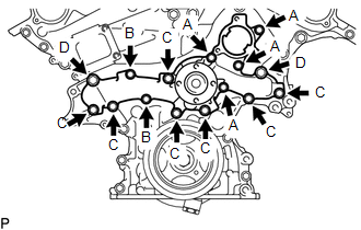
(a) Install the engine water pump assembly and a new gasket to the timing chain cover assembly with the 15 bolts. Torque: for Bolt A and B : 11 N·m {112 kgf·cm, 8 ft·lbf} for Bolt C : 21 N·m {214 kgf·cm, 15 ft·lbf} for Bolt D : 43 N·m {438 kgf·cm, 32 ft·lbf} NOTICE:
|
|
2. INSTALL NO. 2 IDLER PULLEY SUB-ASSEMBLY
(a) Install the 2 No. 2 idler pulley sub-assemblies to the timing chain cover assembly with the 2 bolts.
Torque:
43 N·m {438 kgf·cm, 32 ft·lbf}
3. INSTALL VANE PUMP ASSEMBLY
(a) Install the vane pump assembly to the timing chain cover assembly with the 2 bolts.
Torque:
21 N·m {214 kgf·cm, 15 ft·lbf}
4. INSTALL V-RIBBED BELT TENSIONER ASSEMBLY
.gif)
5. INSTALL COOLER COMPRESSOR ASSEMBLY
(See page )
6. INSTALL FAN SHROUD
7. INSTALL TRANSMISSION OIL COOLER HOSE (for Automatic Transmission)
|
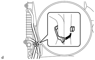
(a) Engage the clamp to install the 2 transmission oil cooler hoses to the fan shroud. |
|
8. CONNECT RADIATOR RESERVE TANK HOSE
9. INSTALL NO. 2 RADIATOR HOSE
10. INSTALL NO. 1 RADIATOR HOSE
11. INSTALL WATER INLET WITH THERMOSTAT SUB-ASSEMBLY
(See page )
 Removal
REMOVAL
PROCEDURE
1. REMOVE WATER INLET WITH THERMOSTAT SUB-ASSEMBLY
(See page )
2. REMOVE NO. 1 RADIATOR HOSE
3. REMOVE NO. 2 RADIATOR HOSE
4. DISCONNECT RADIATOR RESERVE TANK HOSE
5 ...

Other materials:
Road Test
ROAD TEST
1. PROBLEM SYMPTOM CONFIRMATION
(a) Based on the result of the customer problem analysis, try to reproduce the
symptoms. If the problem is that the transmission does not shift up or down, or
that the shift point is too high or too low, conduct the following road test referring
to t ...
Inspection
INSPECTION
PROCEDURE
1. INSPECT BRAKE DRUM INSIDE DIAMETER
(a) Using a brake drum gauge or equivalent, measure the inside diameter of the
drum.
Standard inside diameter:
254 mm (10.00 in.)
Maximum inside diameter:
256 mm (10.08 in.)
If the inside diameter is greater than the maximum, r ...
Steering Lock Position Signal Circuit Malfunction (B2285)
DESCRIPTION
This DTC is stored when the steering lock position signal sent by the steering
lock ECU (steering lock actuator or upr bracket assembly) via direct line and the
steering lock position signal sent via LIN communication do not match.
HINT:
When the cable is disconnected and reconnec ...
