Toyota Tacoma (2015-2018) Service Manual: Entire Combination Meter does not Operate
DESCRIPTION
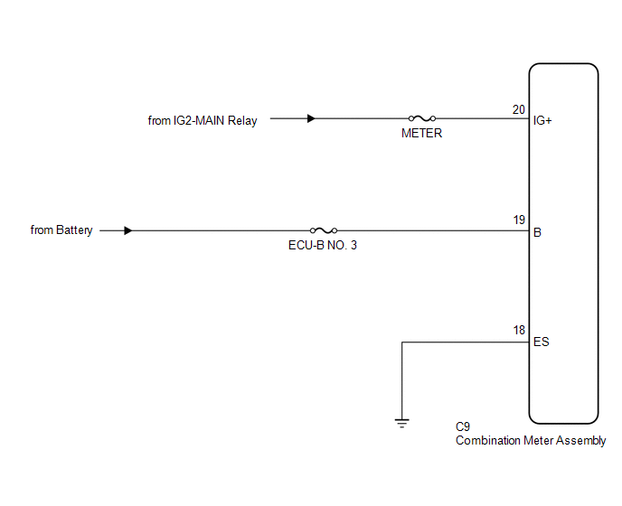
This circuit is the power source circuit for the meter. This circuit provides two types of power sources, one is a constant power source mainly used as a backup power source, and the other is an IG power source mainly used for signal transmission. The constant power source is mainly used as a backup power source for the meter CPU, however, it is also used for CAN communication. If a voltage of 12 V is not applied to terminal IG+ when turning the ignition switch ON, the indicators will not operate.
WIRING DIAGRAM
CAUTION / NOTICE / HINT
CAUTION:
Inspect the fuses for circuits related to this system before performing the following inspection procedure.
PROCEDURE
|
1. |
CHECK HARNESS AND CONNECTOR (COMBINATION METER ASSEMBLY - BATTERY AND BODY GROUND) |
|
(a) Disconnect the combination meter assembly connector. |
|
(b) Measure the voltage according to the value(s) in the table below.
Standard Voltage:
|
Tester Connection |
Switch Condition |
Specified Condition |
|---|---|---|
|
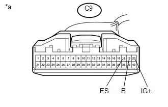
C9-20 (IG+) - Body ground |
Ignition switch ON |
11 to 14 V |
|
C9-19 (B) - Body ground |
Always |
11 to 14 V |
(c) Measure the resistance according to the value(s) in the table below.
Standard Resistance:
|
Tester Connection |
Condition |
Specified Condition |
|---|---|---|
|
C9-18 (ES) - Body ground |
Always |
Below 1 Ω |
|
*a |
Front view of wire harness connector (to Combination Meter Assembly) |
| OK | .gif) |
REPLACE COMBINATION METER ASSEMBLY |
| NG | |
REPAIR OR REPLACE HARNESS OR CONNECTOR |
 Lost Communication with ECM / PCM "A" (U0100,U0129,U0142,U0151,U0163,U023A,U1104)
DESCRIPTION
The combination meter communicates with the ECM, skid control ECU, power steering
ECU, main body ECU (multiplex network body ECU), airbag sensor assembly, navigation
receiver assembly ...
 Speedometer Malfunction
DESCRIPTION
The meter CPU receives vehicle speed signals from the skid control ECU via the
CAN communication system (CAN V1 Bus). The speed sensor detects the wheel speed
and sends the appropriat ...
Other materials:
Compressor Lock Sensor Circuit (B1422/22)
SYSTEM DESCRIPTION
The ECM sends the engine speed signal to the air conditioning amplifier assembly
via CAN communication.
The air conditioning amplifier assembly reads the difference between compressor
speed and engine speed. When the difference becomes too large, the air conditioning
ampli ...
Installation
INSTALLATION
PROCEDURE
1. INSTALL REAR SEATBACK CENTER HINGE SUB-ASSEMBLY
(a) Install the rear seatback center hinge sub-assembly with the 2 bolts.
Torque:
30 N·m {306 kgf·cm, 22 ft·lbf}
2. INSTALL LUGGAGE COMPARTMENT SIDE TRAY
3. INSTALL REAR SEATBACK HINGE SUB-ASSEMBLY
(a) Install ...
USB Audio System Recognition/Play Error
DESCRIPTION
When a USB device or "iPod" is connected to the USB jack of the No. 1 stereo
jack adapter assembly, it must have playable files. The device must also communicate
with and be recognized by the radio and display receiver assembly. This diagnosis
procedure is for when a dev ...
