Toyota Tacoma (2015-2018) Service Manual: Removal
REMOVAL
PROCEDURE
1. PRECAUTION
NOTICE:
After turning the ignition switch off, waiting time may be required before disconnecting the cable from the negative (-) battery terminal. Therefore, make sure to read the disconnecting the cable from the negative (-) battery terminal notices before proceeding with work.
Click here .gif)
2. RECOVER REFRIGERANT FROM REFRIGERATION SYSTEM
Click here
3. DISCONNECT CABLE FROM NEGATIVE BATTERY TERMINAL
NOTICE:
When disconnecting the cable, some systems need to be initialized after the cable is reconnected.
Click here
4. REMOVE FAN AND GENERATOR V BELT (for 2TR-FE)
Click here
5. REMOVE GENERATOR ASSEMBLY (for 2GR-FKS)
Click here
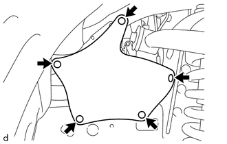
6. REMOVE FRONT UPPER FENDER APRON SEAL
|
(a) Using a clip remover, disengage the 5 clips to remove the front upper fender apron seal. |
|
7. DISCONNECT SUCTION HOSE SUB-ASSEMBLY (for 2TR-FE)
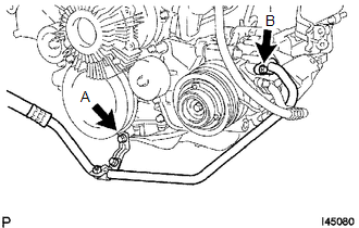
(a) Remove the bolt A.
(b) Remove the bolt B to disconnect the suction hose sub-assembly.
(c) Remove the O-ring from the suction hose sub-assembly.
NOTICE:
Seal the opening of the disconnected parts using vinyl tape to prevent moisture and foreign matter from entering.
8. DISCONNECT SUCTION HOSE SUB-ASSEMBLY (for 2GR-FKS)
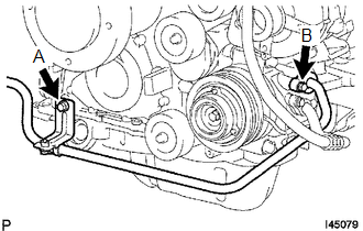
(a) Remove the bolt A.
(b) Remove the bolt A to disconnect the suction hose sub-assembly.
(c) Remove the O-ring from the suction hose sub-assembly.
NOTICE:
Seal the opening of the disconnected parts using vinyl tape to prevent moisture and foreign matter from entering.
9. DISCONNECT DISCHARGE HOSE SUB-ASSEMBLY
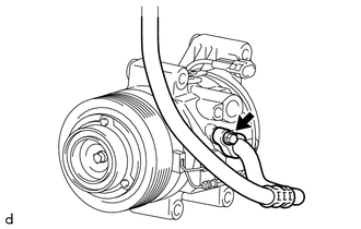
(a) Remove the bolt to disconnect the discharge hose sub-assembly.
(b) Remove the O-ring from the discharge hose sub-assembly.
NOTICE:
Seal the opening of the disconnected parts using vinyl tape to prevent moisture and foreign matter from entering.
10. REMOVE COOLER COMPRESSOR ASSEMBLY (for 2TR-FE)
|
(a) Disconnect the connector. |
|
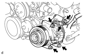
(b) Remove the 2 bolts and 2 nuts.
(c) Using an E8 ''TORX'' socket wrench, remove the 2 stud bolts and cooler compressor assembly.
11. REMOVE COOLER COMPRESSOR ASSEMBLY (for 2GR-FKS)
|
(a) Disconnect the connector. |
|
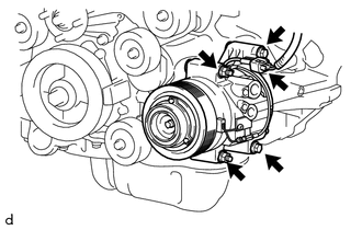
(b) Remove the 2 bolts and 2 nuts.
(c) Using an E8 ''TORX'' socket wrench, remove the 2 stud bolts and cooler compressor assembly.
 Components
COMPONENTS
ILLUSTRATION
ILLUSTRATION
ILLUSTRATION
*1
COMPRESSOR PICK UP SENSOR
*2
MAGNET CLUTCH ASSEMBLY
*3
PRESSURE R ...
 Disassembly
DISASSEMBLY
PROCEDURE
1. REMOVE PRESSURE RELIEF VALVE
(a) Remove the pressure relief valve and O-ring.
2. REMOVE MAGNET CLUTCH ASSEMBLY
(a) Secure the cooler compressor assembly in a vise bet ...
Other materials:
Detachable pole antenna
The antenna can be removed.
■ Removing the antenna
Place the included wrench around the antenna.
When not in use, the wrench is stored in glove box.
Loosen the antenna with the wrench and remove it.
■ Installing the antenna
Tighten the antenna by one hand until it will not t ...
Precaution
PRECAUTION
1. EXPRESSIONS OF IGNITION SWITCH
The type of ignition switch used on this model differs depending on the specifications
of the vehicle. The expressions listed in the table below are used in this section.
Expression
Ignition Switch (Position)
Engine S ...
Removal
REMOVAL
PROCEDURE
1. TABLE OF BOLT, SCREW AND NUT
HINT:
All bolts, screws and nuts relevant to installing and removing the instrument
panel are shown along with their alphabetic codes in the table below.
2. PRECAUTION
NOTICE:
After turning the ignition switch off, waiting time may be requ ...
