Toyota Tacoma (2015-2018) Service Manual: Pressure Control Solenoid "B" Electrical (Shift Solenoid Valve SL2) (P0778)
DESCRIPTION
Changing from 1st to 6th is performed by the ECM turning shift solenoid valves
SL1, SL2, SL3 and SL4 on and off. If an open or short circuit occurs in any of the
shift solenoid valves, the ECM controls the remaining normal shift solenoid valves
to allow the vehicle to be operated (See page .gif) ).
).
|
DTC No. |
DTC Detection Condition |
Trouble Area |
|---|---|---|
|
P0778 |
An open or short circuit (output signal duty is 0% or 100%) is detected by the ECM in the shift solenoid valve SL2 circuit while driving and shifting gears (SL2 output signal duty is more than 3% and less than 100% under normal conditions) (1 trip detection logic). |
|
MONITOR DESCRIPTION
This DTC indicates an open or short in the shift solenoid valve SL2 circuit. The ECM commands gear shifts by turning the shift solenoid valves on or off. When there is an open or short circuit in any of the shift solenoid valve circuits, the ECM detects the problem and illuminates the MIL and stores the DTC. The ECM also performs the fail-safe function and turns the other normal shift solenoid valves on or off. (In case of an open or short circuit, the ECM stops sending current to the circuit.)
While driving and shifting gears, if the ECM detects an open or short in the
shift solenoid valve SL2 circuit, the ECM determines there is a malfunction (See
page ).
MONITOR STRATEGY
|
Related DTCs |
P0778: Shift solenoid valve SL2/Range check |
|
Required sensors/Components |
Shift solenoid valve SL2 |
|
Frequency of operation |
Continuous |
|
Duration |
1 sec. |
|
MIL operation |
Immediately |
|
Sequence of operation |
None |
TYPICAL ENABLING CONDITIONS
All:|
The monitor will run whenever the following DTCs are not stored |
None |
|
Solenoid current cut status |
Not cut |
|
Ignition switch |
ON |
|
Starter |
OFF |
|
Battery voltage |
12 V or higher |
|
Battery voltage |
10 V or higher, and below 12 V |
|
Target current |
Below 0.75 A |
|
Battery voltage |
8 V or higher |
|
Target current |
0.25 A or higher |
TYPICAL MALFUNCTION THRESHOLDS
One of the following conditions is met: Condition (A), (B) or (C)
Condition (A) and (B):|
Output duty cycle |
100% or more |
|
Output duty cycle |
0% or less |
COMPONENT OPERATING RANGE
|
Output duty cycle |
More than 3%, and less than 100% |
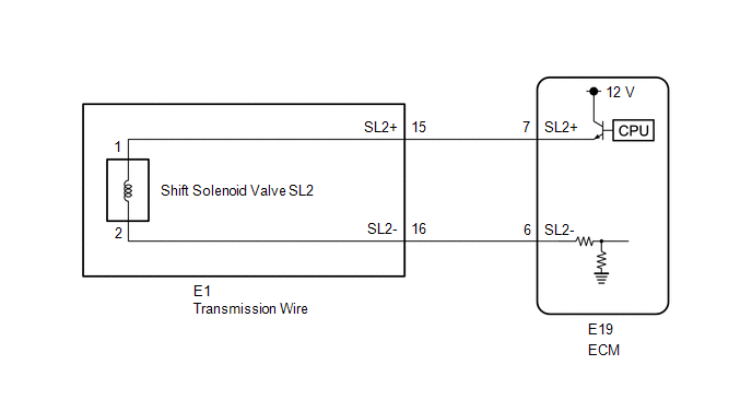
WIRING DIAGRAM
CAUTION / NOTICE / HINT
NOTICE:
- Perform the universal trip to clear permanent DTCs (See page
).
- Perform registration and/or initialization when parts related to the
automatic transmission are replaced (See page
).
HINT:
- The following table shows normal operation of the shift solenoid valve
SL2 when the shift lever is in D:
ECM commanded gear
1st
2nd
3rd
4th
5th
6th
Shift solenoid valve SL2
OFF
OFF
OFF
ON
ON
ON
- After the repair, clear the DTCs and perform the following procedure
to check that DTCs are not output.
- Perform the D Position Shift Test in Road Test.
- Check for DTCs again (See page
).
PROCEDURE
|
1. |
INSPECT TRANSMISSION WIRE (SHIFT SOLENOID VALVE SL2) |
|
(a) Disconnect the E1 transmission wire connector. |
|
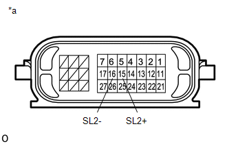
(b) Measure the resistance according to the value(s) in the table below.
Standard Resistance:
|
Tester Connection |
Condition |
Specified Condition |
|---|---|---|
|
15 (SL2+) - 16 (SL2-) |
20°C (68°F) |
5.0 to 5.6 Ω |
|
15 (SL2+) - Body ground |
Always |
10 kΩ or higher |
|
16 (SL2-) - Body ground |
Always |
10 kΩ or higher |
|
*a |
Component without harness connected (Transmission Wire) |
| NG | .gif) |
GO TO STEP 3 |
|
.gif)
|
2. |
CHECK HARNESS AND CONNECTOR (TRANSMISSION WIRE - ECM) |
|
(a) Disconnect the ECM connector. |
|
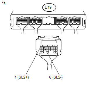
(b) Measure the resistance according to the value(s) in the table below.
Standard Resistance:
|
Tester Connection |
Condition |
Specified Condition |
|---|---|---|
|
E19-7 (SL2+) - E19-6 (SL2-) |
20°C (68°F) |
5.0 to 5.6 Ω |
|
E19-7 (SL2+) - Body ground |
Always |
10 kΩ or higher |
|
E19-6 (SL2-) - Body ground |
Always |
10 kΩ or higher |
|
*a |
Rear view of wire harness connector (to ECM) |
| OK | |
REPLACE ECM |
| NG | |
REPAIR OR REPLACE HARNESS OR CONNECTOR |
|
3. |
INSPECT SHIFT SOLENOID VALVE SL2 |
|
(a) Remove shift solenoid valve SL2 (See page
|
|
.png)
(b) Measure the resistance according to the value(s) in the table below.
Standard Resistance:
|
Tester Connection |
Condition |
Specified Condition |
|---|---|---|
|
1 - 2 |
20°C (68°F) |
5.0 to 5.6 Ω |
(c) Apply 12 V battery voltage to the shift solenoid valve and check that the valve moves and makes an operating noise.
OK:
|
Measurement Condition |
Specified Condition |
|---|---|
|
Valve moves and makes an operating noise |
|
*1 |
Shift Solenoid Valve SL2 |
| OK | |
REPLACE TRANSMISSION WIRE |
| NG | |
REPLACE SHIFT SOLENOID VALVE SL2 |
 Torque Converter Clutch Pressure Control Solenoid Control Circuit Electrical
(Shift Solenoid Valve SLU) (P2759)
Torque Converter Clutch Pressure Control Solenoid Control Circuit Electrical
(Shift Solenoid Valve SLU) (P2759)
DESCRIPTION
Refer to the system description for DTC P2757 (See page
).
DTC No.
DTC Detection Condition
Trouble Area
P2759
Open or short ...
 Pressure Control Solenoid "C" Performance (Shift Solenoid Valve SL3) (P0796)
SYSTEM DESCRIPTION
The ECM uses the vehicle speed signal and signals from the transmission revolution
sensors (NT, SP2) to detect the actual gear (1st, 2nd, 3rd, 4th, 5th or 6th gear).
The ECM com ...
Other materials:
System Diagram
SYSTEM DIAGRAM
Communication Table
Sender
Receiver
Signal
Communication Method
Power window regulator master switch assembly*1
Main Body ECU (Multiplex Network Body ECU)
Door control switch signal
...
Using the interior lights
Interior lights list
Interior light
Personal lights (Access Cab and
Double Cab models)
■Illuminated entry system
When the interior light switch is in the DOOR position, the interior light automatically
turns on/off according to whether the doors are locked/unlocked and whether the ...
Center Differential Lock Position Switch (C1282)
DESCRIPTION
DTC C1282 is stored only in test mode.
DTC Code
DTC Detection Condition
Trouble Area
C1282
Stored during test mode.
Harness or connector
Transfer system
Skid control ECU (master cylinder sole ...
