Toyota Tacoma (2015-2018) Service Manual: Components
COMPONENTS
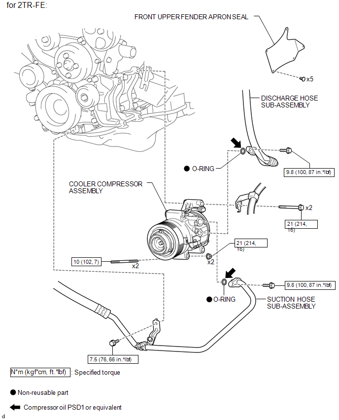
ILLUSTRATION
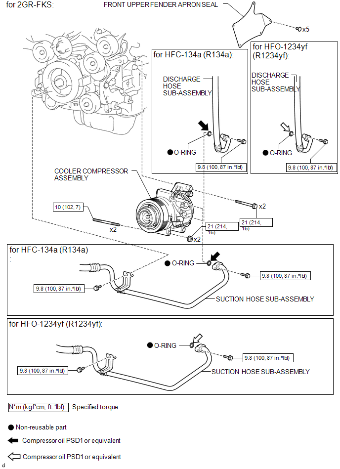
ILLUSTRATION
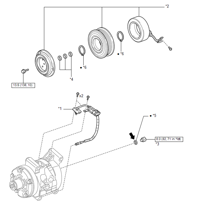
ILLUSTRATION
|
*1 |
COMPRESSOR PICK UP SENSOR |
*2 |
MAGNET CLUTCH ASSEMBLY |
|
*3 |
PRESSURE RELIEF VALVE |
*4 |
COMPRESSOR SPACER |
|
*5 |
O-RING |
*6 |
SNAP RING |
.png) |
N*m (kgf*cm, ft.*lbf): Specified torque |
â—Ź |
Non-reusable part |
.png) |
Compressor oil PSD 1 or equivalent |
- |
- |
 Compressor
...
 Removal
REMOVAL
PROCEDURE
1. PRECAUTION
NOTICE:
After turning the ignition switch off, waiting time may be required before disconnecting
the cable from the negative (-) battery terminal. Therefore, make ...
Other materials:
System Description
SYSTEM DESCRIPTION
1. DESCRIPTION
A part-time 2-speed VF2CM transfer uses a touch select 2-4 and high-low
system, enabling the driver to switch between 2WD, H4 and L4 modes by turning
the transfer position switch.
Through these switch signals, the 4 wheel drive control ECU actua ...
Parts Location
PARTS LOCATION
ILLUSTRATION
ILLUSTRATION
ILLUSTRATION
ILLUSTRATION
...
Front Radar Sensor (C1A10)
DESCRIPTION
When an internal malfunction is detected in the millimeter wave radar sensor
assembly, DTC C1A10 is stored.
DTC No.
Detection Item
DTC Detection Condition
Trouble Area
C1A10
Front Radar Sensor
When the ...
