Toyota Tacoma (2015-2018) Service Manual: Removal
REMOVAL
PROCEDURE
1. REMOVE FRONT NO. 2 EXHAUST PIPE ASSEMBLY (for 2GR-FKS)
.gif)
2. REMOVE PROPELLER SHAFT HEAT INSULATOR BRACKET SUB-ASSEMBLY
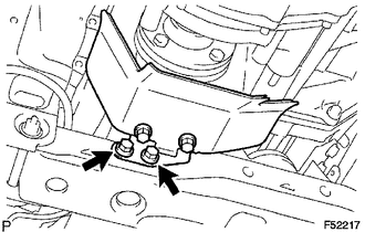
(a) Remove the 2 bolts and propeller shaft heat insulator bracket.
3. REMOVE FRONT PROPELLER SHAFT ASSEMBLY
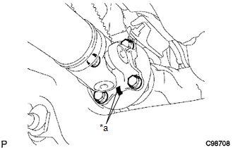
(a) Place matchmarks on the propeller shaft flange and differential flange.
Text in Illustration|
*a |
Matchmark |
(b) Remove the 4 nuts, 4 bolts, 4 washers and front propeller shaft.
|
(c) Place matchmarks on the propeller shaft flange and transfer flange. Text in Illustration
|
|
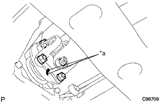
(d) Remove the 4 nuts, 4 washers and front propeller shaft.
 Components
COMPONENTS
ILLUSTRATION
...
 Disassembly
DISASSEMBLY
PROCEDURE
1. INSPECT FRONT PROPELLER SHAFT UNIVERSAL JOINT SPIDER BEARING
(a) Check the spider bearings for wear and damage.
(b) Check each spider bearing's axial play by turning t ...
Other materials:
Disassembly
DISASSEMBLY
PROCEDURE
1. INSPECT 3RD GEAR THRUST CLEARANCE
(a) Using a dial indicator, measure the 3rd gear thrust clearance.
Standard clearance:
0.200 to 0.490 mm (0.0079 to 0.0192 in.)
If the clearance is outside the specification, replace the 3rd gear,
thrust washer, c ...
Vehicle Speed Tolerance Malfunction (C1AA2)
DESCRIPTION
The forward recognition camera receives vehicle speed tolerance signals from
the combination meter assembly. If the combination meter assembly detects a vehicle
speed tolerance malfunction signal, it informs the forward recognition camera via
CAN communication, and DTC C1AA2 is st ...
Components
COMPONENTS
ILLUSTRATION
*A
w/o Woofer
*B
w/ Woofer
*1
LUGGAGE COMPARTMENT SIDE TRAY LH
*2
LUGGAGE COMPARTMENT SIDE TRAY RH
ILLUSTRATION
*1
COWL SIDE TRIM BOARD LH
...
