Toyota Tacoma (2015-2018) Service Manual: Disassembly
DISASSEMBLY
PROCEDURE
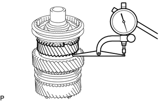
1. INSPECT 3RD GEAR THRUST CLEARANCE
|
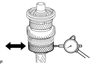
(a) Using a dial indicator, measure the 3rd gear thrust clearance. Standard clearance: 0.200 to 0.490 mm (0.0079 to 0.0192 in.) If the clearance is outside the specification, replace the 3rd gear, thrust washer, clutch hub or shaft. HINT: Replace the part or parts determined to be the most likely cause of the problem. |
|
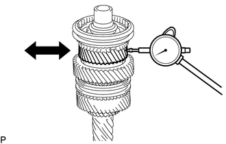
2. INSPECT 3RD GEAR RADIAL CLEARANCE
|
(a) Using a dial indicator, measure the 3rd gear radial clearance. Standard clearance: 0.0150 to 0.065 mm (0.0006 to 0.0025 in.) If the clearance is outside the specification, replace the 3rd gear, 3rd gear needle roller bearing or shaft. HINT: Replace the part or parts determined to be the most likely cause of the problem. |
|
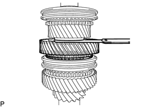
3. INSPECT 6TH GEAR SUB-ASSEMBLY THRUST CLEARANCE
|
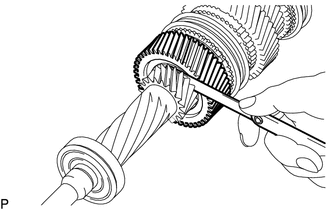
(a) Using a feeler gauge, measure the 6th gear sub-assembly thrust clearance. Standard clearance: 0.150 to 0.580 mm (0.0059 to 0.0228 in.) If the clearance is outside the specification, replace the 6th gear sub-assembly, thrust washer, clutch hub or shaft. HINT: Replace the part or parts determined to be the most likely cause of the problem. |
|
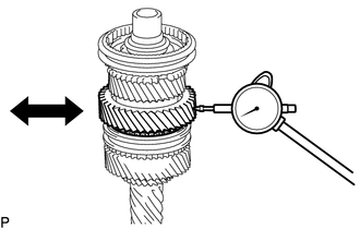
4. INSPECT 6TH GEAR SUB-ASSEMBLY RADIAL CLEARANCE
|
(a) Using a dial indicator, measure the 6th gear sub-assembly radial clearance. Standard clearance: 0.015 to 0.067 mm (0.0006 to 0.0026 in.) If the clearance is outside the specification, replace the 6th gear sub-assembly, 6th gear needle roller bearing or shaft. HINT: Replace the part or parts determined to be the most likely cause of the problem. |
|
5. INSPECT 5TH GEAR THRUST CLEARANCE
|
(a) Using a feeler gauge, measure the 5th gear thrust clearance. Standard clearance: 0.150 to 0.410 mm (0.0059 to 0.0161 in.) If the clearance is outside the specification, replace the 6th gear sub-assembly, 6th gear needle roller bearing or shaft. HINT: Replace the part or parts determined to be the most likely cause of the problem. |
|
6. INSPECT 5TH GEAR RADIAL CLEARANCE
|
(a) Using a dial indicator, measure the 5th gear radial clearance. Standard clearance: 0.013 to 0.054 mm (0.0006 to 0.0021 in.) If the clearance is outside the specification, replace the 5th gear, thrust washer, clutch hub or shaft. HINT: Replace the part or parts determined to be the most likely cause of the problem. |
|
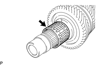
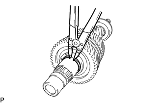
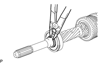
7. REMOVE NO. 2 CLUTCH HUB SETTING SHAFT SNAP RING
|
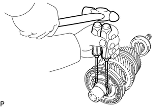
(a) Using 2 screwdrivers and a hammer, tap off the No. 2 clutch hub setting shaft snap ring. HINT: Use a piece of cloth to prevent the snap ring from flying off. |
|
8. REMOVE NO. 2 TRANSMISSION HUB SLEEVE
(a) Remove the No. 2 transmission hub sleeve from the No. 2 transmission clutch hub.
9. REMOVE NO. 1 SYNCHROMESH SHIFTING KEY
(a) Remove the No. 1 synchromesh shifting key from the No. 2 transmission clutch hub.
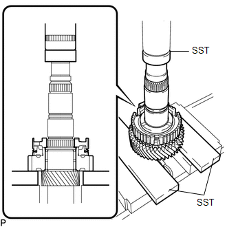
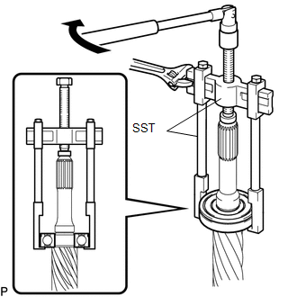
10. REMOVE NO. 2 TRANSMISSION CLUTCH HUB
|
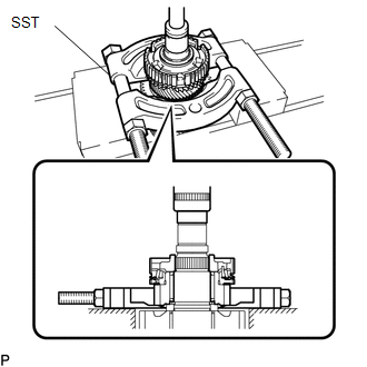
(a) Using SST and a press, remove the No. 2 transmission clutch hub, No. 3 synchronizer ring set and 3rd gear from the input shaft. SST: 09555-55010 SST: 09950-60010 09951-00410 NOTICE:
|
|
11. REMOVE 3RD GEAR NEEDLE ROLLER BEARING
|
(a) Remove the 3rd gear needle roller bearing from the input shaft. |
|
12. REMOVE 3RD GEAR SPACER
(a) Remove the 3rd gear spacer from the input shaft.
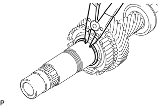
13. REMOVE GEAR THRUST WASHER SHAFT SNAP RING
|
(a) Using a snap ring expander, remove the gear thrust washer shaft snap ring from the input shaft. |
|
14. REMOVE 3RD GEAR THRUST WASHER
(a) Remove the 3rd gear thrust washer from the input shaft.
15. REMOVE GEAR THRUST WASHER STRAIGHT PIN
(a) Remove the gear thrust washer straight pin from the input shaft.
16. REMOVE 6TH GEAR SUB-ASSEMBLY
(a) Remove the 6th gear sub-assembly from the input shaft.
17. REMOVE NO. 3 SYNCHRONIZER RING
(a) Remove the No. 3 synchronizer ring from the No. 3 transmission clutch hub.
18. REMOVE 6TH GEAR NEEDLE ROLLER BEARING
(a) Remove the 6th gear needle roller bearing from the input shaft.
19. REMOVE 6TH GEAR SPACER
(a) Remove the 6th gear spacer from the input shaft.
20. REMOVE NO. 2 TRANSMISSION HUB SLEEVE
(a) Remove the No. 2 transmission hub sleeve from the No. 3 transmission clutch hub.
21. REMOVE NO. 1 SYNCHROMESH SHIFTING KEY
(a) Remove the No. 1 synchromesh shifting key from the No. 3 transmission clutch hub.
22. REMOVE CLUTCH HUB SET SHAFT SNAP RING
|
(a) Using a snap ring expander, remove the clutch hub set shaft snap ring from the input shaft. |
|
23. REMOVE 5TH GEAR
|
(a) Using SST and a press, remove the 5th gear and No. 3 transmission clutch hub from the input shaft. SST: 09527-20011 SST: 09950-60010 09951-00410 NOTICE: Support the input shaft so that it does not fall. |
|
24. REMOVE 5TH GEAR NEEDLE ROLLER BEARING
(a) Remove the 5th gear needle roller bearing from the input shaft.
25. REMOVE FRONT INPUT SHAFT BEARING
|
(a) Using a snap ring expander, remove the snap ring from the input shaft. |
|
|
(b) Using SST, remove the front input shaft bearing from the input shaft. SST: 09950-40011 09951-04010 09952-04010 09953-04020 09954-04020 09955-04031 09957-04010 09958-04011 SST: 09950-60010 09951-00180 |
|
 Components
COMPONENTS
ILLUSTRATION
ILLUSTRATION
...
 Inspection
INSPECTION
PROCEDURE
1. INSPECT INPUT SHAFT
(a) Using a dial indicator and 2 V-blocks, measure the shaft runout.
Maximum runout:
0.03 mm (0.0012 in.)
If the runout is more than ...
Other materials:
Transponder Key Amplifier
Components
COMPONENTS
ILLUSTRATION
Installation
INSTALLATION
PROCEDURE
1. INSTALL TRANSPONDER KEY COIL
(a) Engage the 2 claws to install the transponder key coil.
(b) Connect the connector.
2. INSTALL UPPER STEERING COLUMN COVER
(S ...
Removal
REMOVAL
PROCEDURE
1. PRECAUTION
NOTICE:
After turning the ignition switch off, waiting time may be required before disconnecting
the cable from the negative (-) battery terminal.
Therefore, make sure to read the disconnecting the cable from the negative (-)
battery terminal notices before p ...
Clutch Pedal Switch
On-vehicle Inspection
ON-VEHICLE INSPECTION
PROCEDURE
1. CHECK CLUTCH START SYSTEM
(a) Check that the engine does not start when the clutch pedal is released.
(b) Check that the engine starts when the clutch pedal is fully depressed.
If necessary, replace the clutch start switch assembly.
...
