Toyota Tacoma (2015-2018) Service Manual: Components
COMPONENTS
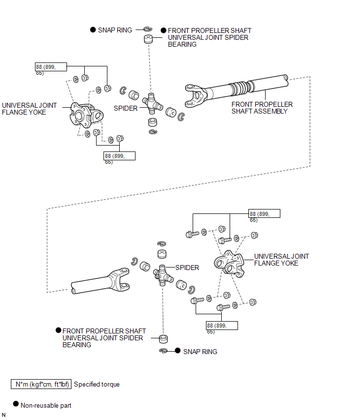
ILLUSTRATION

 Removal
REMOVAL
PROCEDURE
1. REMOVE FRONT NO. 2 EXHAUST PIPE ASSEMBLY (for 2GR-FKS)
2. REMOVE PROPELLER SHAFT HEAT INSULATOR BRACKET SUB-ASSEMBLY
(a) Remove the 2 bolts and propeller shaft heat insu ...
Other materials:
Disassembly
DISASSEMBLY
PROCEDURE
1. REMOVE HOOD BULGE ASSEMBLY (w/ Hood Bulge)
(a) Remove the 4 nuts.
(b) Disengage the clip from back side of the hood panel to remove the hood bulge
assembly together with the air intake guide.
2. REMOVE NO. 2 HOOD BU ...
Installation
INSTALLATION
PROCEDURE
1. INSTALL FRONT SEATBACK HEATER ASSEMBLY
(a) Set the front seatback heater assembly with the name stamp side facing the
front seatback cover.
(b) Install the front seatback heater assembly with 14 new tag pins.
2. INSTALL SEPARATE TYPE FRONT SEATBACK COVER (for Front P ...
Downhill Assist Control system
The downhill assist control system helps to prevent excessive speed on steep
downhill descents.
■ System operation
The system will operate when the vehicle is traveling under 15 mph (25 km/h)
and the front-wheel drive control switch is in the L4 position.
Press the DAC switch. The ind ...
