Toyota Tacoma (2015-2018) Service Manual: Disassembly
DISASSEMBLY
PROCEDURE
1. INSPECT FRONT PROPELLER SHAFT UNIVERSAL JOINT SPIDER BEARING
(a) Check the spider bearings for wear and damage.
(b) Check each spider bearing's axial play by turning the yoke while holding the shaft tightly.
Maximum bearing axial play:
0 to 0.05 mm (0 to 0.002 in.)
2. REMOVE FRONT PROPELLER SHAFT UNIVERSAL JOINT SPIDER BEARING
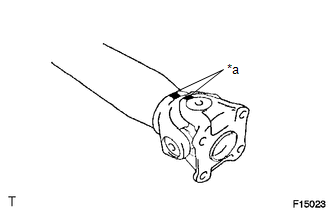
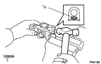
(a) Place matchmarks on the propeller shaft and flange yoke.
Text in Illustration|
*a |
Matchmark |
|
(b) Using a brass bar and a hammer, slightly tap in the spider bearing outer races. |
|
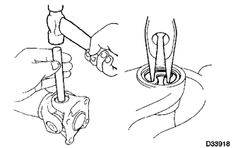
(c) Using needle-nose pliers, remove the 4 snap rings from the grooves.
|
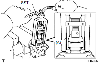
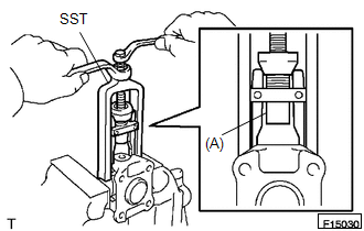
(d) Using SST, push the spider bearing out of the propeller shaft. SST: 09332-25010 HINT: Sufficiently raise the part indicated by (A) so that it does not come into contact with the spider bearing. |
|
|
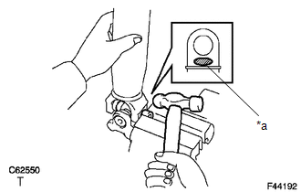
(e) Clamp the spider bearing outer race in a vise and tap off the propeller shaft with a hammer. HINT: Remove the bearing on the opposite side in the same procedure. Text in Illustration
NOTICE: Do not tap the shaft. |
|
|
(f) Install the 2 removed spider bearing outer races onto the spider, and clamp them in a vise. |
|
(g) Using SST, push the bearing out of the yoke.
SST: 09332-25010
HINT:
Sufficiently raise the part indicated by (A) so that it does not come into contact with the bearing.
|
(h) Clamp the outer bearing race in a vise and tap off the flange yoke with a hammer. Text in Illustration
|
|
(i) Remove the spider.
 Removal
REMOVAL
PROCEDURE
1. REMOVE FRONT NO. 2 EXHAUST PIPE ASSEMBLY (for 2GR-FKS)
2. REMOVE PROPELLER SHAFT HEAT INSULATOR BRACKET SUB-ASSEMBLY
(a) Remove the 2 bolts and propeller shaft heat insu ...
 Inspection
INSPECTION
PROCEDURE
1. INSPECT FRONT PROPELLER SHAFT ASSEMBLY
(a) Using a dial indicator, check the propeller shaft runout.
Maximum runout:
0.6 mm (0.024 in.)
If the shaft runout is greater ...
Other materials:
Data Signal Circuit between Stereo Jack Adapter and Extension Module
DESCRIPTION
The No. 1 stereo jack adapter assembly sends the sound data signal or image data
signal from a USB device to the navigation receiver assembly via this circuit.
WIRING DIAGRAM
PROCEDURE
1.
CHECK HARNESS AND CONNECTOR (NAVIGATION RECEIVER ASSEMBLY - NO. 1 STE ...
Precaution
PRECAUTION
1. CAUTION REGARDING INTERFERENCE WITH ELECTRONIC DEVICES
CAUTION:
People with implantable cardiac pacemakers, cardiac resynchronization
therapy-pacemakers or implantable cardioverter defibrillators should keep
away from the smart key system antennas. The radio waves ma ...
Garage door opener
The garage door opener can be trained to operate garage doors, gates, entry
doors, door locks, home lighting systems, security systems, and other devices.
The garage door opener (HomeLinkÂź Universal Transceiver) is manufactured under
license from HomeLinkÂź.
Training the HomeLinkÂź (for U.S. ...
