Toyota Tacoma (2015-2018) Service Manual: Adjustment
ADJUSTMENT
CAUTION / NOTICE / HINT
CAUTION:
Radiofrequency radiation exposure information:
- This equipment complies with FCC radiation exposure limits set forth for an uncontrolled environment.
- This equipment should be kept with minimum distance of 20 cm (7.87 in.) between the radiator (antenna) and your body at all times during adjustment.
- This transmitter must not be co-located or operating in conjunction with any other antenna or transmitter.
PROCEDURE
1. PREPARATION FOR MILLIMETER WAVE RADAR SENSOR ASSEMBLY ADJUSTMENT
(a) Park the vehicle on a level surface where the area in front of the vehicle shown in the illustration is free of metal objects.
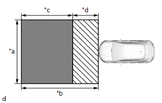
|
*a |
5 m (16.4 ft.) |
|
*b |
6 m (19.7 ft.) |
|
*c |
4 m (13.1 ft.) |
|
*d |
2 m (6.56 ft.) |
.png) |
Do not place any metal objects in this area |
.png) |
Do not place metal objects with a height of more than 50 mm (1.97 in.) in this area |
HINT:
Metal objects with a height of 50 mm (1.97 in.) or less placed within the area shown in the illustration will not affect the adjustment.
(b) Check the levelness of the ground.
(1) Check the levelness of the ground at the 3 points shown in the illustration.
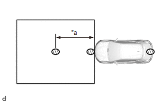
|
*a |
3 m (9.84 ft.) |
|
|
Levelness Check Point |
(2) Place the level on each levelness check point and check that the air bubble of the level is centered.
(c) Adjust the tire inflation pressure to the specified pressure.
Click here .gif)
(d) Clean the radiator grill garnish or millimeter wave radar sensor assembly.
(e) Visually inspect the front of the vehicle.
HINT:
Confirm that there is no damage or deformation.
(f) Check that the radiator grill garnish and millimeter wave radar sensor assembly is clean and there is no dirt or snow covering them.
(g) Visually inspect the front bumper cover, radiator grille sub-assembly and stays.
HINT:
Confirm that there is no damage or deformation.
2. ADJUST MILLIMETER WAVE RADAR SENSOR ASSEMBLY VERTICALLY AND HORIZONTALLY
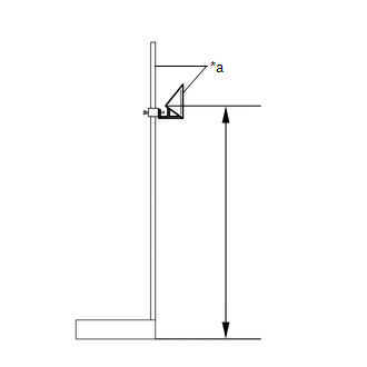
(a) Adjust SST (reflector) height.
|
(1) Adjust SST (reflector) so that the center of SST (reflector) is the same height as the millimeter wave radar sensor assembly. HINT: Make sure to align the center of SST (reflector) with the millimeter wave radar sensor assembly (the center of the emblem). Reference Value:
SST: 09870-60000 09870-60010 SST: 09870-60040 |
|
(b) Place SST (reflector).
(1) Hang a weight with a pointed tip from the center of the tail gate handle, and mark the rear center point of the vehicle (point A) on the ground.

|
*a |
String |
*b |
Weight |
|
*c |
Bilateral Symmetry |
- |
- |
HINT:
Lightly flick the string with your fingers several times to confirm that the string is perpendicular to the ground.
(2) Hang a weight with a pointed tip from the center of the radiator grille garnish, and mark the front center point of the vehicle (point B) on the ground (placement position).
- for Type A:
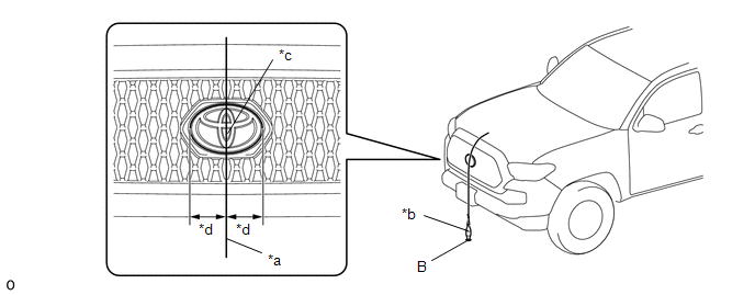
*a
String
*b
Weight
*c
Center
*d
Bilateral Symmetry
- for Type B:
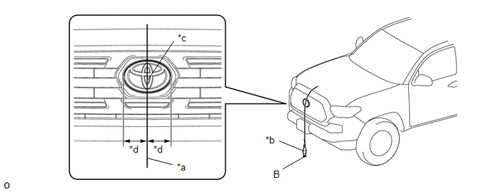
*a
String
*b
Weight
*c
Center
*d
Bilateral Symmetry
- for Type C:
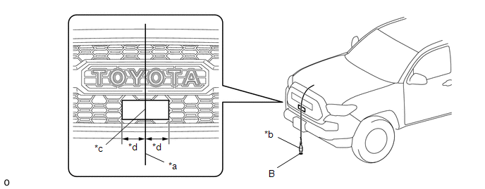
*a
String
*b
Weight
*c
Center
*d
Bilateral Symmetry
HINT:
Lightly flick the string with your fingers several times to confirm that the string is perpendicular to the ground.
(3) Using tape and a string, create a line that connects point B to point A and extends at least 3000 mm (9.84 ft.) beyond the front center point of the vehicle.
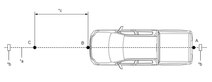
|
*a |
String |
*b |
Tape |
|
*c |
3000 mm (9.84 ft.) |
- |
- |
HINT:
- Make sure the string is taut when securing it with tape.
- Lightly flick the string with your fingers several times to confirm that the string is aligned with point B.
(4) Mark point C (SST (reflector) placement position) at a position 3000 mm (9.84 ft.) from point B.
(5) Place SST (reflector) at point C.
(c) Front Beam Axis Adjustment:
NOTICE:
- Close all of the doors.
- Ensure that nobody enters the adjustment area during the adjustment.
- Do not move or shake the vehicle during adjustment (do not get in or out of the vehicle).
- During the procedure, do not enter the adjustment area.
- Do not turn off the Techstream or ignition switch.
(1) Connect the Techstream to the DLC3.
(2) Turn the ignition switch to ON.
(3) Turn the Techstream on and turn the cruise control system on using the cruise control main switch (ON/OFF button).
(4) Enter the following menus: Body Electrical / Pre-Collision 2 / Utility / Front Beam Axis Adjustment.
(5) According to the display on the Techstream, press "Next".
(6) Perform the adjustment according to the display on the Techstream.
NOTICE:
If an error code is displayed, perform troubleshooting according to the following table, then perform the adjustment again.
|
Error No. |
Error Description |
Cause of Error |
Action to be Taken |
|---|---|---|---|
|
1 |
No target abnormality |
|
Place SST (reflector) in the correct position. (See page 2. MILLIMETER WAVE RADAR SENSOR ASSEMBLY VERTICALLY AND HORIZONTALLY (b) Place SST (reflector)) |
|
Clean the radiator grill garnish and radiator grille sub-assembly or millimeter wave radar sensor assembly. |
|||
|
Dirt, snow or other obstruction is on the surface of the radiator grille sub-assembly or millimeter wave sensor assembly. Check and remove any dirt, snow or other obstruction on the surface of the radiator grille sub-assembly or millimeter wave sensor. |
|||
|
2 |
Target distance abnormality |
|
Place SST (reflector) in the correct position. (See page 2. MILLIMETER WAVE RADAR SENSOR ASSEMBLY VERTICALLY AND HORIZONTALLY (b) Place SST (reflector)) |
|
3 |
Plural targets abnormality |
|
Remove any reflective objects. |
|
Ensure that nobody enters the adjustment area during the adjustment. (See page 1. PREPARATION FOR MILLIMETER WAVE RADAR SENSOR ASSEMBLY ADJUSTMENT) |
|||
|
4 |
Target move abnormality |
|
Place SST (reflector) in the correct position. (See page 2. MILLIMETER WAVE RADAR SENSOR ASSEMBLY VERTICALLY AND HORIZONTALLY (b)Place SST (reflector)) |
|
Perform adjustment in an area with no wind. |
|||
|
Ensure that nobody enters the adjustment area during the adjustment. (See page 1. PREPARATION FOR MILLIMETER WAVE RADAR SENSOR ASSEMBLY ADJUSTMENT) |
|||
|
6 |
Target angle abnormality |
|
Place SST (reflector) in the correct position. (See page 2. MILLIMETER WAVE RADAR SENSOR ASSEMBLY VERTICALLY AND HORIZONTALLY (b)Place SST (reflector)) |
|
Check the condition of the millimeter wave radar sensor assembly. |
|||
|
Check the condition of the sensor, radiator grille sub-assembly and front bumper cover. Check the installation condition of the front bumper cover and radiator grille sub-assembly. |
|||
|
7 |
Radar abnormality |
|
|
|
8 |
Radar dirtiness |
|
Clean the radiator grill garnish and radiator grille sub-assembly or millimeter wave radar sensor assembly. |
|
9 |
Temperature abnormality |
|
Wait until the temperature drops to the operable range (-30 to 70°C). |
|
10 |
Voltage abnormality |
|
Check the battery voltage (specified condition: 10 to 16 V).
|
|
11 |
External communication abnormality |
|
Check the condition of the connectors. |
|
12 |
Radar axis aiming failure upward |
|
Check the condition of the millimeter wave radar sensor assembly. |
|
Check the condition of the sensor and front bumper cover. Check the installation condition of the front bumper cover. |
|||
|
13 |
Radar axis aiming failure downward |
|
Check the condition of the millimeter wave radar sensor assembly. |
|
Check the condition of the sensor and front bumper cover. Check the installation condition of the front bumper cover. |
|||
|
14 |
Vehicle speed abnormality |
|
Ensure that the vehicle remains stationary. |
|
15 |
Other |
|
Perform adjustment again. |
*1: When millimeter wave radar sensor learning is in progress, clear the DTCs and perform beam axis alignment again.
(7) Press the "Exit" button to finish front beam axis adjustment.
(d) Front Beam Axis Misalignment Reading:
NOTICE:
- Close all of the doors.
- Ensure that nobody enters the adjustment area during the adjustment.
- Do not move or shake the vehicle during adjustment (do not get in or out of the vehicle).
- During the procedure, do not enter the adjustment area.
- Do not turn off the Techstream or ignition switch.
(1) Enter the following menus: Body Electrical / Pre-Collision 2 / Utility / Front Beam Axis Misalignment Reading.
(2) According to the display on the Techstream, press "Next".
(3) Perform the adjustment according to the display on the Techstream.
Specified Condition:
|
Vertical |
-0.4 to 0.4 deg |
|
Horizontal |
-0.3 to 0.3 deg |
NOTICE:
If the result is not as specified, perform beam axis adjustment again.
(e) Front Beam Axis Offset Reading:
(1) Enter the following menus: Body Electrical / Pre-Collision 2 / Utility / Front Beam Axis Offset Reading.
(2) According to the display on the Techstream, press "Next".
(3) Perform the adjustment according to the display on the Techstream.
Specified Condition:
|
Vertical learning value |
0 deg |
|
Horizontal learning value |
0 deg |
NOTICE:
If the result is not as specified, perform beam axis adjustment again.
(4) Turn the ignition switch off.
(5) Disconnect the Techstream from the DLC3.
 Components
COMPONENTS
ILLUSTRATION
*A
for Type A
*B
for Type B
*C
for Type C
-
-
*1
M ...
 Removal
REMOVAL
PROCEDURE
1. REMOVE MILLIMETER WAVE RADAR WIRE
(a) for Type A:
(1) Disconnect the 2 connectors.
(2) Using a clip remover, disengage the 4 clamps to remove the millimeter
...
Other materials:
System Diagram
SYSTEM DIAGRAM
Communication Table
Sender ECU
Receiver ECU
Signal
Line
*1: for Vacuum Brake Booster
*2: for Hydraulic Brake Booster
Forward Recognition Camera
Combination Meter Assembly
...
Dtc Check / Clear
DTC CHECK / CLEAR
CHECK FOR DTC
(a) Connect the Techstream to the DLC3.
(b) Turn the ignition switch to ON.
(c) Turn the Techstream on.
(d) Enter the following menus: Body Electrical / Central Gateway / Trouble Codes.
(e) Read the DTCs.
CLEAR DTC
(a) Connect the Techstream to the DLC3.
(b) ...
Disposal
DISPOSAL
CAUTION / NOTICE / HINT
CAUTION:
Before performing pre-disposal deployment of any SRS part, review and closely
follow all applicable environmental and hazardous material regulations. Pre-disposal
deployment may be considered hazardous material treatment.
PROCEDURE
1. PRECAUTION
...
