Toyota Tacoma (2015-2018) Service Manual: Installation
INSTALLATION
CAUTION / NOTICE / HINT
NOTICE:
If the millimeter wave radar sensor assembly has been struck or dropped, replace the millimeter wave radar sensor assembly with a new one.
PROCEDURE
1. INSTALL MILLIMETER WAVE RADAR SENSOR ASSEMBLY
|
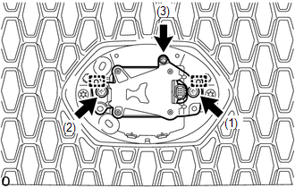
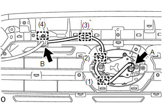
(a) for Type A: (1) Engage the 2 guides. (2) Temporarily install the millimeter wave radar sensor assembly with the 2 bolts and screw. (3) Tighten the 2 bolts and screw in the order shown in the illustration. Torque: Bolt : 2.5 N·m {25 kgf·cm, 22 in·lbf} |
|
|
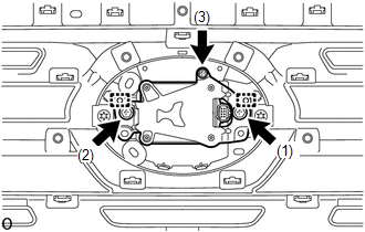
(b) for Type B: (1) Engage the 2 guides. (2) Temporarily install the millimeter wave radar sensor assembly with the 2 bolts and screw. (3) Tighten the 2 bolts and screw in the order shown in the illustration. Torque: Bolt : 2.5 N·m {25 kgf·cm, 22 in·lbf} |
|
|
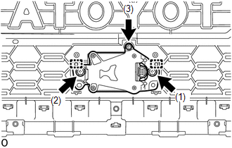
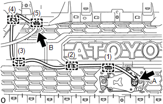
(c) for Type C: (1) Engage the 2 guides. (2) Temporarily install the millimeter wave radar sensor assembly with the 2 bolts and screw. (3) Tighten the 2 bolts and screw in the order shown in the illustration. Torque: Bolt : 2.5 N·m {25 kgf·cm, 22 in·lbf} |
|
2. INSTALL MILLIMETER WAVE RADAR WIRE
|
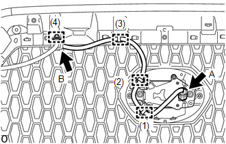
(a) for Type A: (1) Connect the connector A. (2) Engage the 4 clamps to install the millimeter wave radar wire in the order shown in the illustration. (3) Connect the connector B. |
|
|
(b) for Type B: (1) Connect the connector A. (2) Engage the 4 clamps to install the millimeter wave radar wire in the order shown in the illustration. (3) Connect the connector B. |
|
|
(c) for Type C: (1) Connect the connector A. (2) Engage the 5 clamps to install the millimeter wave radar wire in the order shown in the illustration. (3) Connect the connector B. |
|
3. ADJUST MILLIMETER WAVE RADAR SENSOR ASSEMBLY
(a) When the millimeter wave radar sensor assembly is replaced, adjust the millimeter wave radar sensor assembly.
Click here .gif)
 Removal
REMOVAL
PROCEDURE
1. REMOVE MILLIMETER WAVE RADAR WIRE
(a) for Type A:
(1) Disconnect the 2 connectors.
(2) Using a clip remover, disengage the 4 clamps to remove the millimeter
...
 Differential
...
Other materials:
Sound Signal Circuit between Radio Receiver and Stereo Jack Adapter
DESCRIPTION
The No. 1 stereo jack adapter assembly sends the sound signal from an external
device to the radio and display receiver assembly via this circuit.
If there is an open or short in the circuit, sound cannot be heard from the speakers
even if there is no malfunction in the radio and d ...
Removal
REMOVAL
PROCEDURE
1. REMOVE INSTRUMENT PANEL SUB-ASSEMBLY
(See page
)
2. REMOVE NO. 3 HEATER TO REGISTER DUCT
3. REMOVE INSTRUMENT PANEL WIRE ASSEMBLY
(a) Using a screwdriver with its tip wrapped in protective tape, release
the 3 airbag connector locks.
Text in Illustr ...
Problem Symptoms Table
PROBLEM SYMPTOMS TABLE
HINT:
Use the table below to help determine the cause of problem symptoms.
If multiple suspected areas are listed, the potential causes of the symptoms
are listed in order of probability in the "Suspected Area" column of the
table.
Check each ...
