Toyota Tacoma (2015-2018) Service Manual: Interior Illumination Light
Components
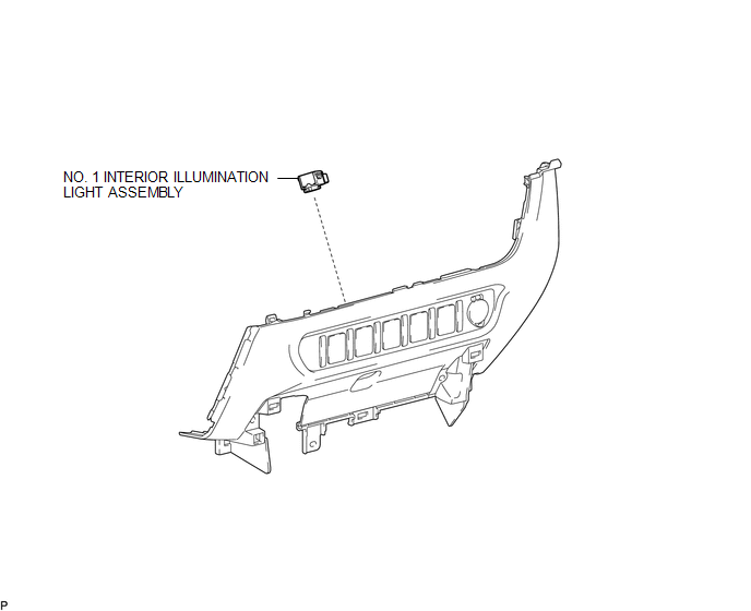
COMPONENTS
ILLUSTRATION
Removal
REMOVAL
PROCEDURE
1. REMOVE INSTRUMENT PANEL LOWER CENTER FINISH PANEL
(See page .gif) )
)
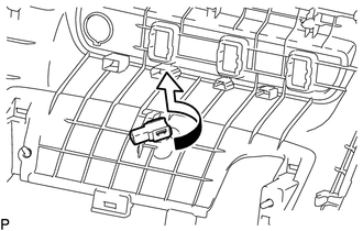
2. REMOVE NO. 1 INTERIOR ILLUMINATION LIGHT ASSEMBLY
|
(a) Turn the No. 1 interior illumination light assembly in the direction indicated by the arrow in the illustration to remove it. |
|
Installation
INSTALLATION
PROCEDURE
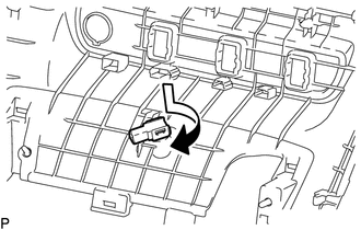
1. INSTALL NO. 1 INTERIOR ILLUMINATION LIGHT ASSEMBLY
|
(a) Turn the No. 1 interior illumination light assembly in the direction indicated by the arrow shown in the illustration to install it. |
|
2. INSTALL INSTRUMENT PANEL LOWER CENTER FINISH PANEL
(See page .gif) )
)
 Installation
INSTALLATION
PROCEDURE
1. INSTALL CENTER STOP LIGHT ASSEMBLY (for Bulb Type Stop Light)
(a) Install the 3 center stop light bulbs to the 3 center stop light sockets.
(b) Turn the 3 cent ...
 License Plate Light Assembly
Components
COMPONENTS
ILLUSTRATION
Removal
REMOVAL
CAUTION / NOTICE / HINT
HINT:
Use the same procedure for both the LH and RH sides.
The procedure described below is for the ...
Other materials:
Disassembly
DISASSEMBLY
PROCEDURE
1. REMOVE STEERING GEAR OUTLET RETURN TUBE
(a) Using a union nut wrench, remove the steering gear outlet return tube.
2. REMOVE STEERING TURN PRESSURE TUBE
(a) Using a union nut wrench, remove the 2 pressure tubes.
(b) Remove the 4 O-rings from the pressure tubes.
3. ...
Clutch Start Cancel Switch
Inspection
INSPECTION
PROCEDURE
1. INSPECT CLUTCH START CANCEL SWITCH ASSEMBLY
(a) Using an ohmmeter, check that there is resistance between terminals
2 and 4.
Standard:
10 kΩ or higher
If the result is not as specified, replace the clutch start cancel switch.
...
Sound Signal Circuit between Radio Receiver and Stereo Jack Adapter
DESCRIPTION
The No. 1 stereo jack adapter assembly sends the sound signal from an external
device to the radio and display receiver assembly via this circuit.
If there is an open or short in the circuit, sound cannot be heard from the speakers
even if there is no malfunction in the radio and d ...
