Toyota Tacoma (2015-2018) Service Manual: Interior Light Auto Cut Circuit
DESCRIPTION
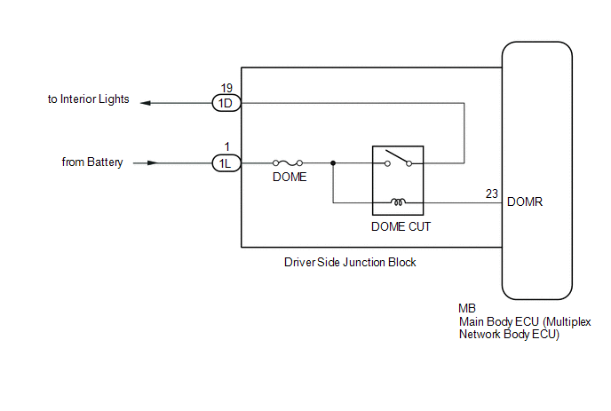
When the battery saving control operates, the main body ECU (multiplex network body ECU) controls the operation of the DOME CUT relay, that is built in to the driver side junction block, to turn off the interior lights.
WIRING DIAGRAM
CAUTION / NOTICE / HINT
NOTICE:
- Inspect the fuses for circuits related to this system before performing the following inspection procedure.
- If the main body ECU (multiplex network body ECU) is replaced, refer
to Registration (See page
.gif) ).*1
).*1
- *1: w/ Smart Key System
PROCEDURE
|
1. |
PERFORM ACTIVE TEST USING TECHSTREAM (RELAY FOR INTERIOR LIGHT AUTO CUT FUNCTION) |
(a) Connect the Techstream to the DLC3.
(b) Turn the ignition switch to ON.
(c) Turn the Techstream on.
(d) Enter the following menus: Body Electrical / Main Body / Active Test.
(e) Perform the Active Test according to the display on the Techstream.
Main Body|
Tester Display |
Test Part |
Control Range |
Diagnostic Note |
|---|---|---|---|
|
Relay for Interior Light Auto Cut Function |
DOME CUT relay |
ON/OFF |
|
OK:
DOME CUT relay operates.
| OK | .gif) |
PROCEED TO NEXT SUSPECTED AREA SHOWN IN PROBLEM SYMPTOMS TABLE |
|
.gif)
|
2. |
CHECK HARNESS AND CONNECTOR (DOME FUSE - DRIVER SIDE JUNCTION BLOCK) |
(a) Disconnect the 1L driver side junction block connector.
(b) Measure the voltage according to the value(s) in the table below.
Standard Voltage:
|
Tester Connection |
Condition |
Specified Condition |
|---|---|---|
|
1L-1 - Body ground |
Always |
11 to 14 V |
| NG | |
REPAIR OR REPLACE HARNESS OR CONNECTOR |
|
|
3. |
REPLACE DRIVER SIDE JUNCTION BLOCK |
(a) Replace the driver side junction block (See page
).
|
|
4. |
PERFORM ACTIVE TEST USING TECHSTREAM (RELAY FOR INTERIOR LIGHT AUTO CUT FUNCTION) |
(a) Connect the Techstream to the DLC3.
(b) Turn the ignition switch to ON.
(c) Turn the Techstream on.
(d) Enter the following menus: Body Electrical / Main Body / Active Test.
(e) Perform the Active Test according to the display on the Techstream.
Main Body|
Tester Display |
Test Part |
Control Range |
Diagnostic Note |
|---|---|---|---|
|
Relay for Interior Light Auto Cut Function |
DOME CUT relay |
ON/OFF |
|
OK:
DOME CUT relay operates.
| OK | |
END (DRIVER SIDE JUNCTION BLOCK WAS DEFECTIVE) |
| NG | |
REPLACE MAIN BODY ECU (MULTIPLEX NETWORK BODY ECU) |
 Hazard Warning Switch Circuit
DESCRIPTION
The combination meter assembly receives information signals from the telltale
light assembly (hazard warning signal switch).
WIRING DIAGRAM
CAUTION / NOTICE / HINT
NOTICE:
Inspect ...
 Interior Light Circuit
DESCRIPTION
The illuminated entry system controls the interior lights.
WIRING DIAGRAM
CAUTION / NOTICE / HINT
NOTICE:
Inspect the fuses for circuits related to this system before perfor ...
Other materials:
Back-up Power Source Circuit
DESCRIPTION
The back-up power source circuit for the air conditioning amplifier assembly
is shown below. Power is supplied even when the ignition switch is off. The power
is used for diagnostic trouble code memory, etc.
WIRING DIAGRAM
CAUTION / NOTICE / HINT
NOTICE:
Inspect the fuses for ...
How To Proceed With Troubleshooting
CAUTION / NOTICE / HINT
HINT:
The ECM of this system is connected to the CAN communication system.
Therefore, before starting troubleshooting, make sure to check that there
is no trouble in the CAN and multiplex communication system.
*: Use the Techstream.
PROCEDURE
...
Rear Differential Lock Solenoid Circuit Low (P17C0)
DESCRIPTION
This DTC is output when a malfunction is detected due to a short to ground occurring
in the differential lock coil drive circuit of the rear differential.
DTC No.
Detection Item
DTC Detection Condition
Trouble Area
P17C0
...
