Toyota Tacoma (2015-2018) Service Manual: Reassembly
REASSEMBLY
PROCEDURE
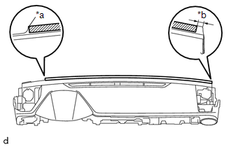
1. INSTALL INSTRUMENT PANEL CUSHION
|
(a) Install a new instrument panel cushion as shown in the illustration. Text in Illustration
HINT:
|
|
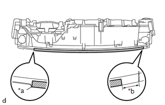
2. INSTALL NO. 4 INSTRUMENT PANEL CUSHION
|
(a) Install a new No. 4 instrument panel cushion as shown in the illustration. Text in Illustration
HINT:
|
|
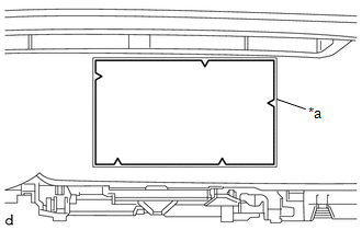
3. INSTALL NO. 2 INSTRUMENT PANEL CUSHION
|
(a) Align a new No. 2 instrument panel cushion with the silencer markings on the instrument panel sub-assembly and install the No. 2 instrument panel cushion using hot-melt glue. Text in Illustration
|
|
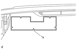
4. INSTALL NO. 1 INSTRUMENT PANEL CUSHION
|
(a) Align a new No. 1 instrument panel cushion with the silencer markings on the instrument panel sub-assembly and install the No. 1 instrument panel cushion using hot-melt glue. Text in Illustration
|
|
5. INSTALL NO. 1 METER HOOD RETAINER
HINT:
Use the same procedure as for the opposite side.
|
(a) Engage the guide to install the No. 1 meter hood retainer. |
|
.png)
(b) Install the screw <D>.
6. INSTALL NO. 1 INSTRUMENT PANEL PIN
HINT:
Use the same procedure as for the opposite side.
|
(a) Engage the guide to install the No. 1 instrument panel pin. |
|
.png)
(b) Install the screw <F>.
7. INSTALL INSTRUMENT PANEL PASSENGER WITHOUT DOOR AIRBAG ASSEMBLY
.gif)
8. INSTALL ANTENNA CORD SUB-ASSEMBLY
9. INSTALL NAVIGATION ANTENNA ASSEMBLY (w/ Navigation System)
10. INSTALL NETWORK GATEWAY ECU
11. INSTALL NO. 1 INSTRUMENT PANEL REGISTER SUB-ASSEMBLY
|
(a) Engage the 3 guides and 6 claws to install the No. 1 instrument panel register sub-assembly. |
|
.png)
12. INSTALL DEFROSTER NOZZLE ASSEMBLY
|
(a) Engage the 3 guides to install the defroster nozzle assembly. |
|
.png)
(b) Install the 3 screws <F>.
13. INSTALL SIDE NO. 2 DEFROSTER NOZZLE DUCT
|
(a) Engage the 2 claws and 2 guides to install the No. 2 defroster nozzle duct. |
|
.png)
(b) Install the 2 screws <F>.
14. INSTALL SIDE NO. 1 DEFROSTER NOZZLE DUCT
|
(a) Engage the 2 claws and 2 guides to install the No. 1 defroster nozzle duct. |
|
.png)
(b) Install the 2 screws <F>.
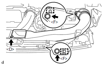
15. INSTALL NO. 2 HEATER TO REGISTER DUCT
|
(a) Engage the 2 guides to install the No. 2 heater to register duct. |
|
.png)
(b) Install the 2 screws <F> and screw <D>.
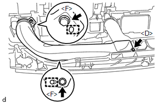
16. INSTALL NO. 3 HEATER TO REGISTER DUCT
|
(a) Engage the 2 guides to install the No. 3 heater to register duct. |
|
(b) Install the 2 screws <F> and screw <D>.
17. INSTALL NO. 1 HEATER TO REGISTER DUCT
|
(a) Engage the 2 guides to install the No. 1 heater to register duct. |
|
(b) Install the 2 screws <F> and screw <D>.
 Installation
INSTALLATION
PROCEDURE
1. INSTALL INSTRUMENT PANEL SUB-ASSEMBLY
(a) Engage the 5 guides to install the instrument panel sub-assembly.
(b) Engage the clamps and connect the connectors.
(c) Insta ...
 Lighting
...
Other materials:
Terminals Of Ecu
TERMINALS OF ECU
Text in Illustration
*a
Component without harness connected
(Skid Control ECU [Brake Actuator Assembly])
-
-
Terminal No. (Symbol)
Terminal Description
1 (GND2)
Pump motor g ...
Precaution
PRECAUTION
1. CAUTION REGARDING INTERFERENCE WITH ELECTRONIC DEVICES
CAUTION:
People with implantable cardiac pacemakers, cardiac resynchronization
therapy-pacemakers or implantable cardioverter defibrillators should keep
away from the smart key system antennas. The radio waves ma ...
How To Proceed With Troubleshooting
CAUTION / NOTICE / HINT
HINT:
Use this procedure to troubleshoot the seat heater system.
*: Use the Techstream.
PROCEDURE
1.
VEHICLE BROUGHT TO WORKSHOP
NEXT
2.
...
