Toyota Tacoma (2015-2018) Service Manual: Removal
REMOVAL
PROCEDURE
1. REMOVE NO. 2 ENGINE UNDER COVER SUB-ASSEMBLY (w/ Off Road Package)
2. REMOVE NO. 1 ENGINE UNDER COVER SUB-ASSEMBLY
3. DRAIN ENGINE COOLANT
.gif)
4. REMOVE RADIATOR GRILLE
(See page )
5. REMOVE EXHAUST MANIFOLD SUB-ASSEMBLY RH
(See page )
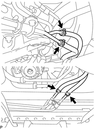
6. REMOVE NO. 2 OIL COOLER INLET HOSE AND NO. 2 OIL COOLER OUTLET HOSE
NOTICE:
When disconnecting the hoses from the tube, support the tube by hand and be careful to prevent the tube from being deformed.
HINT:
Use a container to catch any ATF.
|
(a) Slide the 2 clips and disconnect the No. 2 oil cooler inlet hose and No. 2 oil cooler outlet hose from the No. 1 oil cooler inlet tube and No. 1 oil cooler outlet tube. |
|
(b) Slide the 2 clips and remove the No. 2 oil cooler inlet hose and No. 2 oil cooler outlet hose from the transmission oil thermostat.
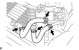
7. REMOVE TRANSMISSION OIL COOLER ASSEMBLY
NOTICE:
When disconnecting the hoses from the tube, support the tube by hand and be careful to prevent the tube from being deformed.
HINT:
Use a container to catch any ATF and coolant.
|
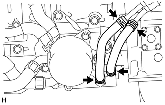
(a) Slide the 2 clips and disconnect the 2 water by-pass hoses from the transmission oil cooler assembly. |
|
|
(b) Slide the 2 clips and disconnect the No. 1 oil cooler inlet hose and No. 1 oil cooler outlet hose from the automatic transmission assembly. |
|
(c) Slide the 2 clips and remove the No. 1 oil cooler inlet hose and No. 1 oil cooler outlet hose from the transmission oil thermostat.
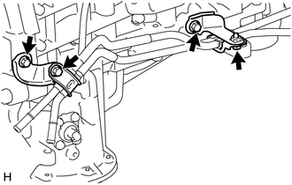
(d) Remove the 3 bolts and transmission oil cooler assembly with transmission oil thermostat from the automatic transmission assembly.
|
(e) Remove the 3 bolts and transmission oil cooler assembly from the transmission oil thermostat. |
|
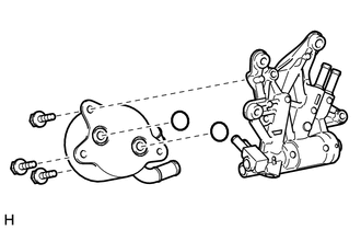
(f) Remove the 2 O-rings from the grooves of transmission oil cooler assembly.
8. REMOVE NO. 3 OIL COOLER INLET HOSE AND NO. 3 OIL COOLER OUTLET HOSE
NOTICE:
When disconnecting the hoses from the tube, support the tube by hand and be careful to prevent the tube from being deformed.
HINT:
Use a container to catch any ATF.
|
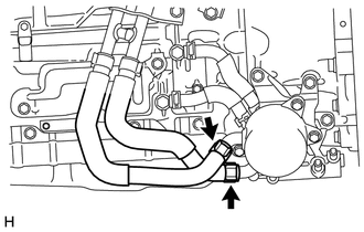
(a) Slide the 2 clips and disconnect the No. 3 oil cooler inlet hose and No. 3 oil cooler outlet hose from the oil cooler tube. |
|
(b) Slide the 2 clips and remove the No. 3 oil cooler inlet hose and No. 3 oil cooler outlet hose from the No. 1 oil cooler inlet tube and No. 1 oil cooler outlet tube.
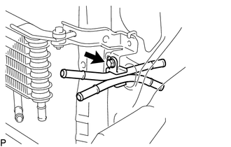
9. REMOVE NO. 1 OIL COOLER INLET TUBE AND NO. 1 OIL COOLER OUTLET TUBE
HINT:
Use a container to catch any ATF.
|
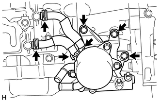
(a) Remove the 2 bolts, 2 flexible hose clamps, No. 1 oil cooler inlet tube and No. 1 oil cooler outlet tube. |
|
(b) Remove the 2 bolts and 2 oil cooler tube clamps from the automatic transmission assembly and engine assembly.
10. REMOVE NO. 4 OIL COOLER INLET HOSE AND NO. 4 OIL COOLER OUTLET HOSE
NOTICE:
When disconnecting the hoses from the tube, support the tube by hand and be careful to prevent the tube from being deformed.
HINT:
Use a container to catch any ATF.
|
(a) Detach the claw to open the clamp. Text in Illustration
|
|
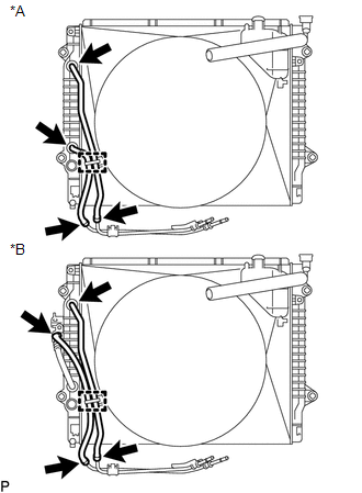
(b) Slide the 2 clips and disconnect the No. 4 oil cooler inlet hose and No. 4 oil cooler outlet hose from the oil cooler tube.
(c) w/o Air Cooled Transmission Oil Cooler:
(1) Slide the 2 clips and remove the No. 4 oil cooler inlet hose and No. 4 oil cooler outlet hose from the radiator assembly.
(d) w/ Air Cooled Transmission Oil Cooler:
(1) Slide the 2 clips and remove the No. 4 oil cooler inlet hose and No. 4 oil cooler outlet hose from the radiator assembly and No.1 oil cooler tube sub-assembly.
11. REMOVE NO. 5 OIL COOLER OUTLET HOSE (w/ Air Cooled Transmission Oil Cooler)
NOTICE:
When disconnecting the hoses from the tube, support the tube by hand and be careful to prevent the tube from being deformed.
HINT:
Use a container to catch any ATF.
|
(a) Slide the clip and disconnect the No. 5 oil cooler outlet hose from the radiator assembly. |
|
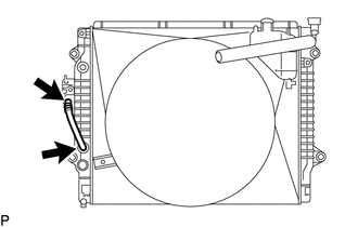
(b) Slide the clip and remove the No. 5 oil cooler outlet hose from the No.1 oil cooler tube sub-assembly.
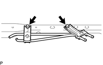
12. REMOVE OIL COOLER TUBE
|
(a) Remove the 2 bolts and oil cooler tube from the vehicle body. |
|
13. REMOVE NO. 6 OIL COOLER INLET HOSE AND NO. 6 OIL COOLER OUTLET HOSE (w/ Air Cooled Transmission Oil Cooler)
NOTICE:
When disconnecting the hoses from the tube, support the tube by hand and be careful to prevent the tube from being deformed.
HINT:
Use a container to catch any ATF.
|
(a) Slide the 2 clips and disconnect the No. 6 oil cooler inlet hose and No. 6 oil cooler outlet hose from the No.1 oil cooler tube sub-assembly. |
|
(b) Slide the 2 clips and remove the No. 6 oil cooler inlet hose and No. 6 oil cooler outlet hose from the oil cooler assembly.
14. REMOVE NO. 1 OIL COOLER TUBE SUB-ASSEMBLY (w/ Air Cooled Transmission Oil Cooler)
|
(a) Remove the bolt and No.1 oil cooler tube sub-assembly from the oil cooler bracket. |
|
15. REMOVE OIL COOLER ASSEMBLY (w/ Air Cooled Transmission Oil Cooler)
|
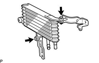
(a) Remove the 3 bolts and oil cooler assembly from the vehicle body. |
|
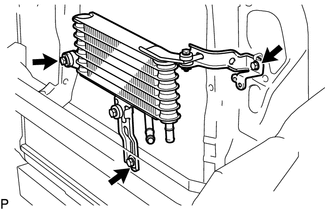
|
(b) Remove the 2 bolts and 2 oil cooler brackets from the oil cooler assembly. |
|
 Components
COMPONENTS
ILLUSTRATION
ILLUSTRATION
ILLUSTRATION
ILLUSTRATION
ILLUSTRATION
...
 Installation
INSTALLATION
PROCEDURE
1. INSTALL OIL COOLER ASSEMBLY (w/ Air Cooled Transmission Oil Cooler)
(a) Install the 2 oil cooler brackets to the oil cooler assembly with the 2 bolts.
Torque:
5.5 N·m ...
Other materials:
All Doors LOCK/UNLOCK Functions do not Operate Via Door Control Switch
DESCRIPTION
The main body ECU (multiplex network body ECU) receives switch signals from the
door control switch assembly on the front passenger door and activates the door
lock motor on each door according to these signals.
WIRING DIAGRAM
PROCEDURE
1.
READ VALUE USIN ...
Vehicle Information Not Obtained (C1A02)
DESCRIPTION
When a new millimeter wave radar sensor assembly is installed, it receives vehicle
specification information (destination, steering wheel position, 2WD or 4WD, etc.)
from the main body ECU (multiplex network body ECU) and stores the information.
DTC C1A02 is stored when the millime ...
Air Outlet Control Servo Motor
Inspection
INSPECTION
PROCEDURE
1. INSPECT MODE CONTROL SERVO MOTOR
(a) Inspect the servo motor operation.
(1) When 12V is applied between terminals 4 (IGN) and 1 (GND), and 0V
is applied between terminals 2 (SIG) and 1 (GND), check that the line connecting
the 2 notches ...
