Toyota Tacoma (2015-2018) Service Manual: Components
COMPONENTS
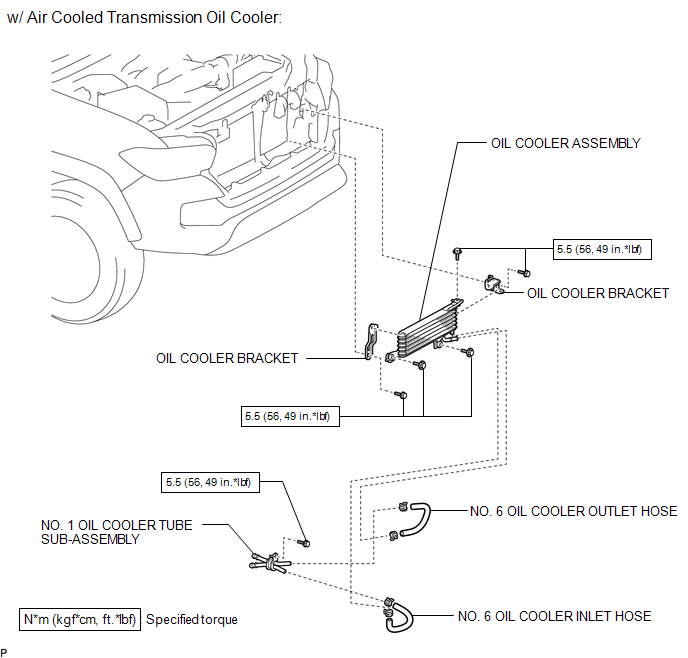
ILLUSTRATION
ILLUSTRATION
ILLUSTRATION
ILLUSTRATION
ILLUSTRATION

 Removal
REMOVAL
PROCEDURE
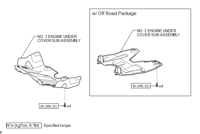
1. REMOVE NO. 2 ENGINE UNDER COVER SUB-ASSEMBLY (w/ Off Road Package)
2. REMOVE NO. 1 ENGINE UNDER COVER SUB-ASSEMBLY
3. DRAIN ENGINE COOLANT
4. REMOVE RADIATOR GRILLE
(See ...
Other materials:
Pressure Control Solenoid "G" Electrical (Shift Solenoid Valve SL4) (P2810)
DESCRIPTION
Changing from 1st to 6th is performed by the ECM turning shift solenoid valves
SL1, SL2, SL3 and SL4 on and off. If an open or short circuit occurs in any of the
shift solenoid valves, the ECM controls the remaining normal shift solenoid valves
to allow the vehicle to be operated ...
Diagnosis System
DIAGNOSIS SYSTEM
CHECK DLC3
(a) Check the DLC3.
Click here
FUNCTION OF WARNING INDICATOR AND MESSAGE
(a) If the pre-collision system is not functioning properly, the driver is warned
by the PCS warning light and a warning message displayed on the multi-information
display.
Mas ...
Removal
REMOVAL
CAUTION / NOTICE / HINT
HINT:
Use the same procedure for both the RH and LH side.
The procedure described below is for the LH side.
PROCEDURE
1. REMOVE REAR ACCESS PANEL WEATHERSTRIP
2. REMOVE LAP BELT OUTER ANCHOR COVER
3. REMOVE ACCESS PANEL INSIDE HANDLE BEZ ...
