Toyota Tacoma (2015-2018) Service Manual: Parking Brake Switch
Components
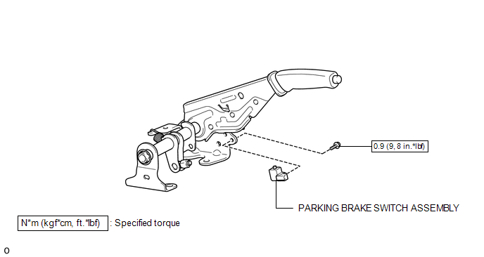
COMPONENTS
ILLUSTRATION
Inspection
INSPECTION
PROCEDURE
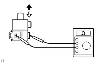
1. INSPECT PARKING BRAKE SWITCH ASSEMBLY
(a) Check the resistance.
(1) Measure the resistance according to the value(s) in the table below.
 Text in Illustration
 |
On |
.png) |
Off |
Standard Resistance:
|
Tester Connection |
Switch Condition |
Specified Condition |
|---|---|---|
|
Switch connector terminal - Switch body |
On (Shaft not pressed) |
Below 1 Ω |
|
Off (Shaft pressed) |
10 kΩ or higher |
If the result is not as specified, replace the parking brake switch assembly.
Installation
INSTALLATION
PROCEDURE
1. INSTALL PARKING BRAKE SWITCH ASSEMBLY
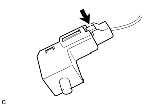
(a) Connect the connector to the parking brake switch assembly.
(b) Install the parking brake switch assembly to the parking brake lever with the screw.
Torque:
0.9 N·m {9 kgf·cm, 8 in·lbf}
2. INSTALL REAR CONSOLE BOX ASSEMBLY
(See page .gif) )
)
Removal
REMOVAL
PROCEDURE
1. REMOVE REAR CONSOLE BOX ASSEMBLY
(See page .gif) )
)
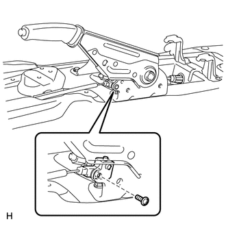
2. REMOVE PARKING BRAKE SWITCH ASSEMBLY
|
(a) Remove the screw and parking brake switch assembly from the parking brake lever. |
|
|
(b) Disconnect the connector. |
|
 Parking Brake Lever
Components
COMPONENTS
ILLUSTRATION
ILLUSTRATION
Installation
INSTALLATION
PROCEDURE
1. INSTALL PARKING BRAKE SWITCH ASSEMBLY
2. INSTALL PARKING BRAKE LEVER SUB-ASSEMBLY
(a) Install ...
 Parking Brake System
Adjustment
ADJUSTMENT
PROCEDURE
1. INSPECT PARKING BRAKE LEVER TRAVEL
(a) Fully pull the parking brake lever to engage the parking brake.
(b) Release the lever to disengage the parking brake.
...
Other materials:
Inspection
INSPECTION
PROCEDURE
1. INSPECT INPUT SHAFT
(a) Using a dial indicator and 2 V-blocks, measure the shaft runout.
Maximum runout:
0.03 mm (0.0012 in.)
If the runout is more than the maximum, replace the input shaft.
HINT:
Measure the 3 areas shown in the illustration wit ...
Terminals Of Ecm
TERMINALS OF ECM
1. ECM
HINT:
The standard voltage between each pair of ECM terminals is shown in the table
below. In the table, first follow the information under "Condition". Look under
"Terminal No. (Symbol)" for the terminals to be inspected. The standard voltage
b ...
Main Switch Power Source Circuit
DESCRIPTION
This circuit supplies power to the wireless charger main switch (mobile wireless
charger switch) and illuminates the switch indicator light when the wireless charger
main switch (mobile wireless charger switch) is turned on.
WIRING DIAGRAM
CAUTION / NOTICE / HINT
NOTICE:
Inspe ...
