Toyota Tacoma (2015-2018) Service Manual: Installation
INSTALLATION
PROCEDURE
1. INSTALL OIL COOLER ASSEMBLY (w/ Air Cooled Transmission Oil Cooler)
(a) Install the 2 oil cooler brackets to the oil cooler assembly with the 2 bolts.
Torque:
5.5 N·m {56 kgf·cm, 49 in·lbf}
|
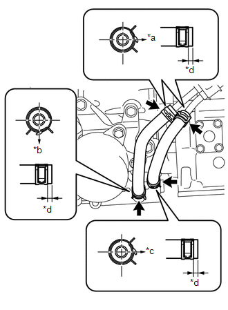
(b) Install the oil cooler assembly to the vehicle body with the 3 bolts in the order shown in the illustration. Torque: 5.5 N·m {56 kgf·cm, 49 in·lbf} |
|
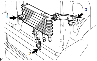
2. INSTALL NO. 1 OIL COOLER TUBE SUB-ASSEMBLY (w/ Air Cooled Transmission Oil Cooler)
(a) Install the No.1 oil cooler tube sub-assembly to the oil cooler bracket with the bolt.
Torque:
5.5 N·m {56 kgf·cm, 49 in·lbf}
3. INSTALL NO. 6 OIL COOLER INLET HOSE AND NO. 6 OIL COOLER OUTLET HOSE (w/ Air Cooled Transmission Oil Cooler)
NOTICE:
- When connecting the hoses to the tube, support the tube by hand and be careful to prevent the tube from being deformed.
- Make sure to install the clips so that the spool fitting is not overlapped.
(a) Install the No. 6 oil cooler inlet hose and No. 6 oil cooler outlet hose to the oil cooler assembly, and slide the 2 clips to secure them.
NOTICE:
Make sure to install any hose clips without a specific installation direction in a direction that does not interfere with other parts.
(b) Connect the No. 6 oil cooler inlet hose and No. 6 oil cooler outlet hose to the No.1 oil cooler tube sub-assembly, and slide the 2 clips to secure them.
NOTICE:
Make sure to install any hose clips without a specific installation direction in a direction that does not interfere with other parts.
4. INSTALL OIL COOLER TUBE
(a) Install the oil cooler tube to the vehicle body with the 2 bolts.
Torque:
28 N·m {286 kgf·cm, 21 ft·lbf}
5. INSTALL NO. 5 OIL COOLER OUTLET HOSE (w/ Air Cooled Transmission Oil Cooler)
NOTICE:
- When connecting the hoses to the tube, support the tube by hand and be careful to prevent the tube from being deformed.
- Make sure to install the clips so that the spool fitting is not overlapped.
(a) Install the No. 5 oil cooler outlet hose to the No.1 oil cooler tube sub-assembly, and slide the clip to secure it.
NOTICE:
Make sure to install any hose clips without a specific installation direction in a direction that does not interfere with other parts.
(b) Connect the No. 5 oil cooler outlet hose to the radiator assembly, and slide the clip to secure it.
NOTICE:
Make sure to install any hose clips without a specific installation direction in a direction that does not interfere with other parts.
6. INSTALL NO. 4 OIL COOLER INLET HOSE AND NO. 4 OIL COOLER OUTLET HOSE
NOTICE:
- When connecting the hoses to the tube, support the tube by hand and be careful to prevent the tube from being deformed.
- Make sure to install the clips so that the spool fitting is not overlapped.
(a) w/o Air Cooled Transmission Oil Cooler:
(1) Install the No. 4 oil cooler inlet hose and No. 4 oil cooler outlet hose to the radiator assembly, and slide the 2 clips to secure them.
NOTICE:
Make sure to install any hose clips without a specific installation direction in a direction that does not interfere with other parts.
(b) w/ Air Cooled Transmission Oil Cooler:
(1) Install the No. 4 oil cooler inlet hose and No. 4 oil cooler outlet hose to the radiator assembly and No.1 oil cooler tube sub-assembly, and slide the 2 clips to secure them.
NOTICE:
Make sure to install any hose clips without a specific installation direction in a direction that does not interfere with other parts.
(c) Connect the No. 4 oil cooler inlet hose and No. 4 oil cooler outlet hose to the oil cooler tube, and slide the 2 clips to secure them.
NOTICE:
Make sure to install any hose clips without a specific installation direction in a direction that does not interfere with other parts.
(d) Then pass the No. 4 oil cooler inlet hose and No. 4 oil cooler outlet hose through the clamp and close the clamp.
7. INSTALL NO. 1 OIL COOLER INLET TUBE AND NO. 1 OIL COOLER OUTLET TUBE
(a) Install the 2 oil cooler tube clamps to the automatic transmission assembly and engine assembly with the 2 bolts.
Torque:
14 N·m {143 kgf·cm, 10 ft·lbf}
(b) Install the No. 1 oil cooler inlet tube, No. 1 oil cooler outlet tube and 2 flexible hose clamps to the 2 oil cooler tube clamps with the 2 bolts.
Torque:
5.5 N·m {56 kgf·cm, 49 in·lbf}
8. INSTALL NO. 3 OIL COOLER INLET HOSE AND NO. 3 OIL COOLER OUTLET HOSE
NOTICE:
- When connecting the hoses to the tube, support the tube by hand and be careful to prevent the tube from being deformed.
- Make sure to install the clips so that the spool fitting is not overlapped.
(a) Install the No. 3 oil cooler inlet hose and No. 3 oil cooler outlet hose to the No. 1 oil cooler inlet tube and No. 1 oil cooler outlet tube, and slide the 2 clips to secure them.
NOTICE:
Make sure to install any hose clips without a specific installation direction in a direction that does not interfere with other parts.
(b) Connect the No. 3 oil cooler inlet hose and No. 3 oil cooler outlet hose to the oil cooler tube, and slide the 2 clips to secure them.
NOTICE:
Make sure to install any hose clips without a specific installation direction in a direction that does not interfere with other parts.
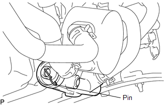
9. INSTALL TRANSMISSION OIL COOLER ASSEMBLY
NOTICE:
- When the transmission oil thermostat is replaced with a new one, pull
out the pin from the new transmission oil thermostat.
- Make sure to install the clips so that the spool fitting is not overlapped.
(a) Coat 2 new O-rings with ATF, and install them to the transmission oil cooler assembly.
(b) Align the transmission oil cooler assembly with the transmission oil thermostat and assemble them with the 3 bolts.
Torque:
14 N·m {143 kgf·cm, 10 ft·lbf}
|
(c) Install the transmission oil cooler assembly with transmission oil thermostat to the automatic transmission assembly with the 3 bolts in the order shown in the illustration. Text in Illustration
Torque: 21 N·m {214 kgf·cm, 15 ft·lbf} |
|
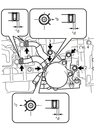
(d) Install the No. 1 oil cooler inlet hose and No. 1 oil cooler outlet hose to the transmission oil thermostat, and slide the 2 clips to secure them.
NOTICE:
Make sure to install any hose clips without a specific installation direction in a direction that does not interfere with other parts.
(e) Connect the No. 1 oil cooler inlet hose and No. 1 oil cooler outlet hose to the automatic transmission assembly, and slide the 2 clips to secure them.
NOTICE:
Make sure to install any hose clips without a specific installation direction in a direction that does not interfere with other parts.
|
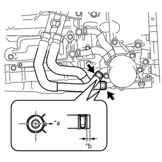
(f) Connect the 2 water by-pass hoses to the transmission oil cooler assembly, and slide the 2 clips to secure them. Text in Illustration
NOTICE: Make sure to install any hose clips without a specific installation direction in a direction that does not interfere with other parts. |
|
10. INSTALL NO. 2 OIL COOLER INLET HOSE AND NO. 2 OIL COOLER OUTLET HOSE
NOTICE:
- When connecting the hoses to the tube, support the tube by hand and be careful to prevent the tube from being deformed.
- Make sure to install the clips so that the spool fitting is not overlapped.
|
(a) Install the No. 2 oil cooler inlet hose and No. 2 oil cooler outlet hose to the transmission oil thermostat, and slide the 2 clips to secure them. Text in Illustration
NOTICE: Make sure to install any hose clips without a specific installation direction in a direction that does not interfere with other parts. |
|
(b) Connect the No. 2 oil cooler inlet hose and No. 2 oil cooler outlet hose to the No. 1 oil cooler inlet tube and No. 1 oil cooler outlet tube, and slide the 2 clips to secure them.
NOTICE:
Make sure to install any hose clips without a specific installation direction in a direction that does not interfere with other parts.
11. INSTALL EXHAUST MANIFOLD SUB-ASSEMBLY RH
(See page .gif)
12. INSTALL RADIATOR GRILLE
(See page )
13. ADD ENGINE COOLANT
14. ADD AUTOMATIC TRANSMISSION FLUID
(See page )
15. INSPECT FOR COOLANT LEAK
16. INSPECT FOR AUTOMATIC TRANSMISSION FLUID LEAK
17. INSTALL NO. 1 ENGINE UNDER COVER SUB-ASSEMBLY
Torque:
30 N·m {306 kgf·cm, 22 ft·lbf}
18. INSTALL NO. 2 ENGINE UNDER COVER SUB-ASSEMBLY (w/ Off Road Package)
Torque:
30 N·m {306 kgf·cm, 22 ft·lbf}
 Removal
REMOVAL
PROCEDURE
1. REMOVE NO. 2 ENGINE UNDER COVER SUB-ASSEMBLY (w/ Off Road Package)
2. REMOVE NO. 1 ENGINE UNDER COVER SUB-ASSEMBLY
3. DRAIN ENGINE COOLANT
4. REMOVE RADIATOR GRILLE
(See ...

Other materials:
Disposal
DISPOSAL
CAUTION / NOTICE / HINT
CAUTION:
Before performing pre-disposal deployment of any SRS part, review and closely
follow all applicable environmental and hazardous material regulations. Pre-disposal
deployment may be considered hazardous material treatment.
PROCEDURE
1. PRECAUTION
...
Entire Combination Meter does not Operate
DESCRIPTION
This circuit is the power source circuit for the meter. This circuit provides
two types of power sources, one is a constant power source mainly used as a backup
power source, and the other is an IG power source mainly used for signal transmission.
The constant power source is main ...
Engine (ignition) switch
■ Engine switch
LOCK
The steering wheel is locked and the key can be removed.
(Vehicles with an automatic transmission: The key can be removed only when the
shift lever is in P.)
ACC
Some electrical components such as the audio system can be used.
ON
All electrical components can ...
