Toyota Tacoma (2015-2018) Service Manual: Components
COMPONENTS
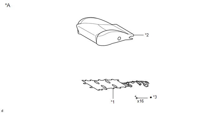
ILLUSTRATION
|
*A |
for Driver Side |
- |
- |
|
*1 |
FRONT SEAT CUSHION HEATER ASSEMBLY |
*2 |
SEPARATE TYPE FRONT SEAT CUSHION COVER |
|
*3 |
TAG PIN |
- |
- |
|
â—Ź |
Non-reusable part |
- |
- |
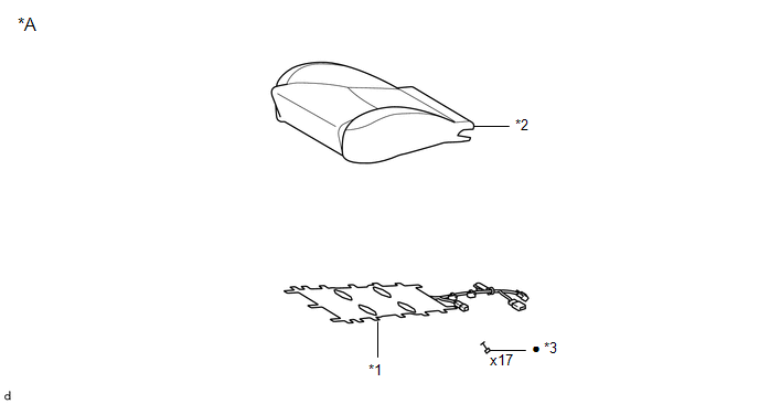
ILLUSTRATION
|
*A |
for Front Passenger Side |
- |
- |
|
*1 |
FRONT SEAT CUSHION HEATER ASSEMBLY |
*2 |
SEPARATE TYPE FRONT SEAT CUSHION COVER |
|
*3 |
TAG PIN |
- |
- |
|
â—Ź |
Non-reusable part |
- |
- |

 Inspection
INSPECTION
PROCEDURE
1. INSPECT FRONT SEAT CUSHION HEATER ASSEMBLY
(a) Check the operation of the front seat cushion heater assembly.
(1) Apply battery voltage and check the operation ...
Other materials:
Television Camera
Components
COMPONENTS
ILLUSTRATION
Installation
INSTALLATION
PROCEDURE
1. INSTALL REAR TELEVISION CAMERA ASSEMBLY
(a) Install the rear television camera assembly with the 2 bolts.
Torque:
5.5 N·m {56 kgf·cm, 49 in·lbf}
(b) Connect the connector.
2. INSTALL TAIL GATE SERVICE HOLE ...
System Diagram
SYSTEM DIAGRAM
Transmitting ECU (Transmitter)
Receiving ECU
Signals
Communication Method
ECM
Skid control ECU
Throttle position signal
Engine speed signal
Accelerator pedal position ...
Reassembly
REASSEMBLY
CAUTION / NOTICE / HINT
HINT:
Use the same procedure for the RH side and LH side.
The following procedure is for the LH side.
When installing a new front wheel opening extension pad or No. 1 front
wheel opening extension pad or No. 2 front wheel opening extension pa ...
