Toyota Tacoma (2015-2018) Service Manual: Reassembly
REASSEMBLY
PROCEDURE
1. INSTALL FRONT LOWER ARM BUSH NO. 1
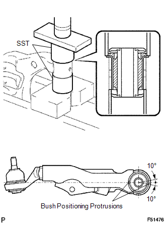
(a) Install a new lower arm bush using SST, a press and steel plate.
SST: 09631-12090
SST: 09631-32020
NOTICE:
Push the lower arm bush in until the bush positioning protrusions come to the positions shown in the illustration.
2. INSTALL FRONT LOWER ARM BUSH NO. 2
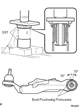
(a) Install a new lower arm bush using SST, a press and steel plate.
SST: 09502-12010
SST: 09631-12090
NOTICE:
Push the lower arm bush in until the bush positioning protrusions come to the positions shown in the illustration.
 Installation
INSTALLATION
PROCEDURE
1. TEMPORARILY TIGHTEN FRONT SUSPENSION LOWER ARM
(a) Align the matchmarks on the camber adjust cam No. 2 and toe adjust cam. Temporarily
tighten the bolt and the nut.
( ...

Other materials:
Customize Parameters
CUSTOMIZE PARAMETERS
PROCEDURE
1. CUSTOMIZE WIRELESS DOOR LOCK CONTROL SYSTEM (w/ Smart Key System)
HINT:
The following items can be customized.
NOTICE:
When the customer requests a change in a function, first make sure that
the function can be customized.
Be sure to make a not ...
Certification ECU Vehicle Information Reading/Writing Process Malfunction (B15F7)
DESCRIPTION
This DTC is stored when items controlled by the certification ECU (smart key
ECU assembly) cannot be customized via the audio and visual system vehicle customization
screen.
HINT:
The certification ECU (smart key ECU assembly) controls the smart key system
related items that are ...
Main Switch Power Source Circuit
DESCRIPTION
This circuit supplies power to the wireless charger main switch (mobile wireless
charger switch) and illuminates the switch indicator light when the wireless charger
main switch (mobile wireless charger switch) is turned on.
WIRING DIAGRAM
CAUTION / NOTICE / HINT
NOTICE:
Inspe ...
