Toyota Tacoma (2015-2018) Service Manual: Installation
INSTALLATION
PROCEDURE
1. TEMPORARILY TIGHTEN FRONT SUSPENSION LOWER ARM
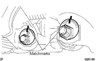
(a) Align the matchmarks on the camber adjust cam No. 2 and toe adjust cam. Temporarily tighten the bolt and the nut.
(b) Install the front lower ball joint attachment, a new nut and a new cotter pin.
Torque:
140 N·m {1428 kgf·cm, 103 ft·lbf}
|
(c) Install the front lower ball joint attachment with the 2 bolts. Torque: 160 N·m {1632 kgf·cm, 118 ft·lbf} |
|
.png)
2. TEMPORARILY TIGHTEN FRONT SHOCK ABSORBER WITH COIL SPRING
.png)
(a) Install the front shock absorber with coil spring, bolt and washer, and temporarily tighten the nut.
3. INSTALL FRONT WHEEL
Torque:
113 N·m {1152 kgf·cm, 83 ft·lbf}
4. STABILIZE FRONT SUSPENSION
(a) Lower the vehicle.
(b) Bounce the vehicle up and down several times to stabilize the suspension.
5. FULLY TIGHTEN FRONT SUSPENSION LOWER ARM
|
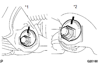
(a) Fully tighten the bolt and nut. Text in Illustration
Torque: for Front Side : 183 N·m {1866 kgf·cm, 135 ft·lbf} for Rear Side : 188 N·m {1917 kgf·cm, 139 ft·lbf} |
|
6. FULLY TIGHTEN FRONT SHOCK ABSORBER WITH COIL SPRING
(a) Fully tighten the nut.
Torque:
83 N·m {846 kgf·cm, 61 ft·lbf}
7. INSPECT AND ADJUST FRONT WHEEL ALIGNMENT
(See page .gif) )
)
 Inspection
INSPECTION
PROCEDURE
1. INSPECT FRONT SUSPENSION LOWER ARM
(a) Flip the ball joint stud back and forth 5 times, as shown in the illustration,
before installing the nut.
(b) Using a torque wren ...
 Reassembly
REASSEMBLY
PROCEDURE
1. INSTALL FRONT LOWER ARM BUSH NO. 1
(a) Install a new lower arm bush using SST, a press and steel plate.
SST: 09631-12090
SST: 09631-32020
NOTICE:
Push the lower arm bu ...
Other materials:
Installation
INSTALLATION
CAUTION / NOTICE / HINT
HINT:
Use the same procedure for both the LH and RH sides.
The procedure described below is for the LH side.
PROCEDURE
1. INSTALL FOG LAMP ASSEMBLY
(a) Engage the 2 guides to install the fog light assembly.
(b) Install the screw.
(c) Con ...
Light Sensor Circuit Malfunction (B1244)
DESCRIPTION
This DTC is output when a failure of the automatic light control sensor circuit
is detected.
DTC Code
DTC Detection Condition
Trouble Area
B1244
When either condition below is met:
Malfunction of light sensor ...
Problem Symptoms Table
PROBLEM SYMPTOMS TABLE
HINT:
Use the table below to help determine the cause of problem symptoms. If multiple
suspected areas are listed, the potential causes of the symptoms are listed in order
of probability in the "Suspected Area" column of the table. Check each symptom by
check ...
