Toyota Tacoma (2015-2018) Service Manual: Front Crankshaft Oil Seal
Components
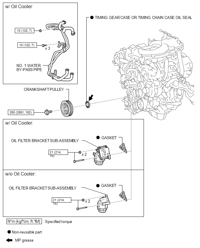
COMPONENTS
ILLUSTRATION
Installation
INSTALLATION
PROCEDURE
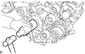
1. INSTALL TIMING GEAR CASE OR TIMING CHAIN CASE OIL SEAL
(a) Apply MP grease to the lip of a new timing gear case or timing chain case oil seal.
|
(b) Using SST and a hammer, tap in the timing gear case or timing chain case oil seal until its surface is flush with the timing chain cover edge. SST: 09226-10010 NOTICE:
|
|
2. INSTALL CRANKSHAFT PULLEY
.gif)
3. INSTALL OIL FILTER BRACKET SUB-ASSEMBLY (w/ Oil Cooler)
4. INSTALL OIL FILTER BRACKET SUB-ASSEMBLY (w/o Oil Cooler)
5. CONNECT NO. 1 WATER BY-PASS PIPE (w/ Oil Cooler)
6. INSTALL RADIATOR ASSEMBLY
(See page )
Removal
REMOVAL
PROCEDURE
1. REMOVE RADIATOR ASSEMBLY
(See page .gif) )
)
2. DISCONNECT NO. 1 WATER BY-PASS PIPE (w/ Oil Cooler)
3. REMOVE OIL FILTER BRACKET SUB-ASSEMBLY (w/ Oil Cooler)
4. REMOVE OIL FILTER BRACKET SUB-ASSEMBLY (w/o Oil Cooler)
5. REMOVE CRANKSHAFT PULLEY
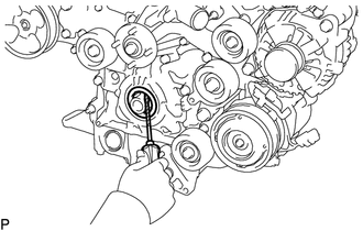
6. REMOVE TIMING GEAR CASE OR TIMING CHAIN CASE OIL SEAL
|
(a) Using a screwdriver, pry out the timing gear case or timing chain case oil seal. NOTICE: Do not damage the surface of the oil seal press fit hole or crankshaft. HINT: Tape the screwdriver tip before use. |
|
 Installation
INSTALLATION
PROCEDURE
1. INSTALL ENGINE COOLANT TEMPERATURE SENSOR
2. INSTALL ENGINE OIL PRESSURE SWITCH ASSEMBLY
3. INSTALL IGNITION COIL ASSEMBLY
4. INSTALL FUEL INJECTOR SEAL
5. ...

Other materials:
Rear Occupant Classification Sensor RH Collision Detection (B1788)
DESCRIPTION
DTC B1788 is set when the occupant detection ECU receives a collision detection
signal, which is sent by the occupant classification sensor rear RH when an accident
occurs.
DTC B1788 is also set when the front seat with adjuster frame assembly RH is
subjected to a strong impact, ...
Removal
REMOVAL
CAUTION / NOTICE / HINT
CAUTION:
Some of these service operations affect the SRS airbag system. Read
the precautionary notices concerning the SRS airbag system before servicing
(See page ).
If the side airbag was deployed, replace the front seat assembly with
a ne ...
Installation
INSTALLATION
PROCEDURE
1. ADJUST COMPRESSOR OIL
(a) for HFC-134a (R134a):
(1) When replacing the compressor and magnetic clutch with new ones, after gradually
discharging the refrigerant gas from the service valve, drain the following volume
of oil from new compressor and magnetic clutch bef ...
