Toyota Tacoma (2015-2018) Service Manual: Microphone Amplifier
Components
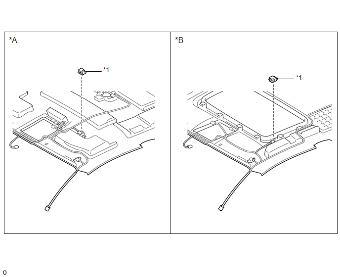
COMPONENTS
ILLUSTRATION
|
*A |
w/o Sliding Roof |
*B |
w/ Sliding Roof |
|
*1 |
TELEPHONE MICROPHONE ASSEMBLY |
- |
- |
Removal
REMOVAL
PROCEDURE
1. REMOVE ROOF HEADLINING ASSEMBLY (for Double Cab)
Click here .gif)
2. REMOVE ROOF HEADLINING ASSEMBLY (for Access Cab)
Click here
3. REMOVE TELEPHONE MICROPHONE ASSEMBLY
|
(a) Disconnect the connector. |
|
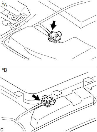
(b) Disengage the 2 claws to remove the telephone microphone assembly.
Installation
INSTALLATION
PROCEDURE
1. INSTALL TELEPHONE MICROPHONE ASSEMBLY
(a) Engage the 2 claws to install the telephone microphone assembly.
(b) Connect the connector.
2. INSTALL ROOF HEADLINING ASSEMBLY (for Double Cab)
Click here .gif)
3. INSTALL ROOF HEADLINING ASSEMBLY (for Access Cab)
Click here
 Installation
INSTALLATION
PROCEDURE
1. INSTALL FRONT NO. 2 SPEAKER ASSEMBLY RH
(a) Connect the connector.
(b) Install the front No. 2 speaker assembly RH with the 2 bolts.
Torque:
8.4 N·m {86 kgf·cm, 74 i ...
 Noise Filter(for 2gr-fks)
Components
COMPONENTS
ILLUSTRATION
Removal
REMOVAL
PROCEDURE
1. DISCONNECT CABLE FROM NEGATIVE BATTERY TERMINAL
2. REMOVE V-BANK COVER
(See page )
3. REMOVE AIR CLEANER ASSEMBLY
(See ...
Other materials:
Removal
REMOVAL
PROCEDURE
1. PRECAUTION
NOTICE:
After turning the ignition switch off, waiting time may be required before disconnecting
the cable from the battery terminal. Therefore, make sure to read the disconnecting
the cable from the battery terminal notice before proceeding with work.
Click ...
If your vehicle has to be stopped in an emergency
Only in an emergency, such as if it becomes impossible to stop the vehicle
in the normal way, stop the vehicle using the following procedure:
Steadily step on the brake pedal
with both feet and firmly depress it.
Do not pump the brake pedal repeatedly as this will increase the effort required ...
System Diagram
SYSTEM DIAGRAM
Circuit Description
Component
Outline
Steering Lock ECU (Steering Lock Actuator or UPR Bracket Assembly)
The steering is locked and unlocked by communicating with the
certification ECU (smart key ECU assembly) via L ...
